Quantcast
Channel: The Engineering Projects
Viewing all 1599 articles
Browse latest View live

Detect Circles in Images Using MATLAB

$
0
0

Liked this post ???
Receive Quality Tutorials in your Inbox in one click:
[STARRATER]

circle detection in image,detect circles in image,matlab circle detectionHello friends, hope you all are fine and having fun with your lives. In today’s post we are gonna see How to detect Circles in Images using MATLAB. It’s quite a simple and basic tutorial but quite helpful as today I was working on a project in which I need to do so but all the codes available online were for detection and tracking of circles in live images. So, I thought to share this one on our site. I have also posted another tutorial Color Detection in Images using MATLAB, so I think its better if you check that one as well.

We all know about MATLAB, which is a great tool for image processing and quite easy as it has a strong Help section. I haven’t posted much tutorials on MATLAB in my blog so from now on I am gonna post tutorial on MATLAB as I get many requests about it. If you have any requests then use our Contact form and send them to us and I will try my best to postrelated tutorials. I personally prefer OpenCV over MATLAB, when it comes to image processing but in OpenCV there’s not much flexibility as in MATLAB. Anyways, let’s start our tutorial which is How to Detect Circles in Images using MATLAB.

Detect Circles in Images Using MATLAB

  • First of all, you are gonna need an Image, in which you are gonna find circles so I used this image of a bike.

circle detection in image,detect circles in image,matlab circle detection

  • As we can see there are two circles in the above image, which are two tyres, so we are gonna detect them now.
  • So, copy the below code and paste it in your MATLAB m file.

ImagePath='TEP.jpg'; %Give Path of your file here
Img=imread(ImagePath);

Img=im2bw(Img(:,:,3));  
Rmin=70;
Rmax=100;  
[centersDark, radiiDark] = imfindcircles(Img, [Rmin Rmax], ...
                                        'ObjectPolarity','bright','sensitivity',0.90)
imagesc(Img);
hold on
viscircles(centersDark, radiiDark,'LineStyle','--');
hold off


  • Now, when you run this code you will get something as shown in below figure:

circle detection in image,detect circles in image,matlab circle detection

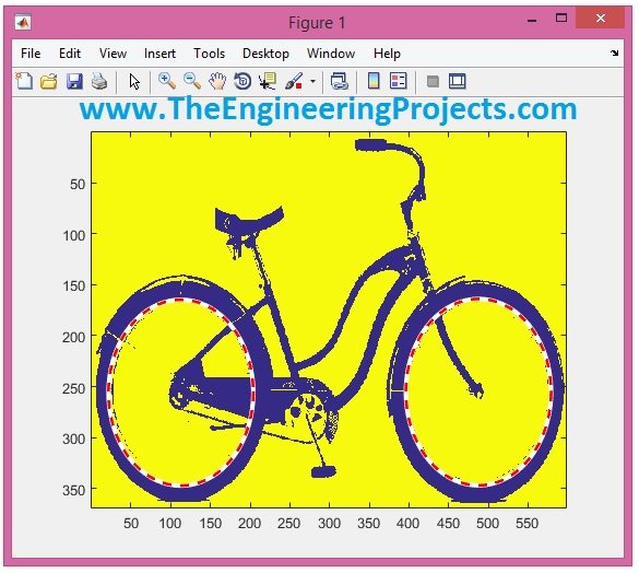
  • As you can see in the above figure, both the circles are now detected and are marked with red and white line.
  • The command, I have used for detecting these circles is imfindcircles , where Rmin and Rmax are the minimum and maximum radius of the circles.
  • It will detect only those circles which will lie in this range and other circles will be ignored.
  • Moreover, the last parameter is for setting the sensitivity of circle detection, which I have given is 0.90.
  • It will also give the center of these circles along with their radii in the command window as shown in below figure:

circle detection in image,detect circles in image,matlab circle detection

  • As, we have detected two circles so the command window is showing the X, Y coordinates of both these circles along with their radii.
  • Now test it and also change the minimum and maximum ranges and you will see you are gonna detect more circles.

It was quite easy but if you have problem in it then ask in comments and I will try my best to solve them. That’s all for today, will meet in next tutorial. Till then take care !!! :)

solar-tracker-projectunnamedunnamed125orange_glossy125orange_glossy

1,324 total views, 32 views today

The post Detect Circles in Images Using MATLAB appeared first on The Engineering Projects.


Color Detection in Images using MATLAB

$
0
0
Liked this post ???
Receive Quality Tutorials in your Inbox in one click:
[STARRATER]

color detection in matlab,matlab color detection,color detection matlab,detect color matlab,detect color in matlabHello friends, hope you all are fine and having fun with your lives. In today’s tutorial, we are gonna see Color Detection in Images using MATLAB. In the previous tutorial, I have posted about How to Detect Circles in Images using MATLAB in which we have detected objects based on their geometrical figure means either they are circle or not but today we are gonna distinguish objects based on their color i.e. whether they are red colored or green colored etc. Its a quite simple tutorial and comes in the basic category. We will first detect the color and then will create a boundary around that object and will also show its XY coordinates as well.

Image processing is an important tool of MATLAB. We can quite easily do the image processing in it using Image Processing toolbox so you need to make sure that your MATLAB must have Image processing toolbox before running this code. So, let’s start with the project.

Color Detection in Images using MATLAB

  • In order to do the Color Detection in Images using MATLAB, first thing we are gonna need is the image itself. 😛
  • So, I designed an image in paint which has different shapes in different colors as shown in below figure:

color detection in matlab,matlab color detection,color detection matlab,detect color matlab,detect color in matlab

  • As you can see in the above figure, there are different shapes in different colors so now we are gonna detect these objects on the basis of their color.
  • Now use the below code and add it in your MATLAB m file:

    data = imread('TEP.jpg');
    diff_im = imsubtract(data(:,:,2), rgb2gray(data));
    %Use a median filter to filter out noise
    diff_im = medfilt2(diff_im, [3 3]);
    diff_im = im2bw(diff_im,0.18);
    
    diff_im = bwareaopen(diff_im,300);
    
    bw = bwlabel(diff_im, 8);
    
    stats = regionprops(bw, 'BoundingBox', 'Centroid');
    
    % Display the image
    imshow(data)
    
    hold on
 
    for object = 1:length(stats)
        bb = stats(object).BoundingBox;
        bc = stats(object).Centroid;
        rectangle('Position',bb,'EdgeColor','r','LineWidth',2)
        plot(bc(1),bc(2), '-m+')
        a=text(bc(1)+15,bc(2), strcat('X: ', num2str(round(bc(1))), ' Y: ', num2str(round(bc(2)))));
        set(a, 'FontName', 'Arial', 'FontWeight', 'bold', 'FontSize', 12, 'Color', 'black');
    end
    
    hold off


  • Now, run your m file and if everything goes fine then you will get an image as shown in below figure:

color detection in matlab,matlab color detection,color detection matlab,detect color matlab,detect color in matlab

  • You can see in the above figure, we have only detected the shapes with green color.
  • The + sign indicates the center of each detected shape.
  • X and Y are the x,y coordinates of the center point of each shape which are shown in black for each detected shape.
  • Now, let’s detect the red color in above figure, so in order to do so what I need to do is to simply change the third value in imsubtract function from 2 to 1.
  • The complete code for red color detection in MATLAB is shown below:

    data = imread('TEP.jpg');
    diff_im = imsubtract(data(:,:,1), rgb2gray(data));
    %Use a median filter to filter out noise
    diff_im = medfilt2(diff_im, [3 3]);
    diff_im = im2bw(diff_im,0.18);
    
    diff_im = bwareaopen(diff_im,300);
    
    bw = bwlabel(diff_im, 8);
    
    stats = regionprops(bw, 'BoundingBox', 'Centroid');
    
    % Display the image
    imshow(data)
    
    hold on
 
    for object = 1:length(stats)
        bb = stats(object).BoundingBox;
        bc = stats(object).Centroid;
        rectangle('Position',bb,'EdgeColor','r','LineWidth',2)
        plot(bc(1),bc(2), '-m+')
        a=text(bc(1)+15,bc(2), strcat('X: ', num2str(round(bc(1))), ' Y: ', num2str(round(bc(2)))));
        set(a, 'FontName', 'Arial', 'FontWeight', 'bold', 'FontSize', 12, 'Color', 'black');
    end
    
    hold off

  • Now, when you run this code in MATLAB, you will get the output as shown in below figure:

color detection in matlab,matlab color detection,color detection matlab,detect color matlab,detect color in matlab

  • Now instead of detecting the green shapes, it has now detected the red shapes in MATLAB.
  • And have also shown their x,y coordinates in black color.
  • Now, finally let’s detect the blue color, in order to do, you now just need to change the third parameter to 3 and it will detect the blue color as shown in below figure:

color detection in matlab,matlab color detection,color detection matlab,detect color matlab,detect color in matlab

  • That’s all for today, and I think its quite an easy one as I mentioned earlier this one is quite basic tutorials. Thanks for reading and I hope it will help you in some ways. :)
solar-tracker-projectunnamedunnamed125orange_glossy125orange_glossy

1,061 total views, 32 views today

The post Color Detection in Images using MATLAB appeared first on The Engineering Projects.

Control Servo Motor with Arduino in Proteus

$
0
0
Liked this post ???
Receive Quality Tutorials in your Inbox in one click:
[STARRATER]

Servo Motor control with arduino,servo motor arduino control,controlling servo motor with arduino , arduino servo motor,interfacing of servo motor with arduinoHello friends, hope you all are fine and having fun with your lives. Today’s post is about Controlling of Servo Motor with Arduino in Proteus ISIS. Servo Motor is quite a common motor used in engineering projects. It is normally used where precise circular motion is required. The reason is because we can move the servo motor at any desired angle which is not possible in case of other motors. For example, I want to move my antenna at precise angle of 90 degree then in that case I can use DC Motor but in DC motor I have to use encoder if I want to move it precisely at 90 degrees. Or I can also move DC motor with delays but in that case it can stop at 85 of 95 something which is not very recise. So, in such cases instead of using DC motor, I will prefer Servo Motor.

I have already posted Angle Control of Servo Motor using 555 Timer in which I have controlled servo motor using 555 timer and another tutorial about Controlling of Servo Motor using PIC Microcotroller in whcih I have controlled it with PIC Microcontroller. And today we are gonna Control Servo Motor with Arduino and will design the simulation in Proteus ISIS. First of all, we will have a look at simple control of servo motor with Arduino in Proteus ISIS and then we will check the control of servo motor with arduino using buttons in which we will move the servo motor to precise angles using buttons. So, let’s get started with it. :)

Simple Control of Servo Motor with Arduino in Proteus

  • First of all, open your Proteus ISIS software and design the below simple circuit.

Servo Motor control with arduino,servo motor arduino control,controlling servo motor with arduino , arduino servo motor,interfacing of servo motor with arduino

  • Servo Motor has three pins, one of them goes to Vcc, other one to GND while the center pin is the controlling pin and goes to any digital pin of Arduino. I have connected the control pin to pin # 4 of my Arduino.
  • Next thing we need to do is to design the code for Arduino. So, open your Arduino software and copy paste the below code in it.

#include <Servo.h> 
 
Servo myservo;  
int pos = 0;    

void setup() 
{ 
  myservo.attach(4);  
}
 
void loop() 
{ 
  for(pos = 0; pos <= 180; pos += 1) 
  {
    myservo.write(pos);              
    delay(15);                      
  } 
  for(pos = 180; pos>=0; pos-=1)     
  {                                
    myservo.write(pos);             
    delay(15);                      
  } 
}
  • Now compile this code and get your hex file. Its the same code as given in the Servo folder of Examples in Arduino software.
  • Upload your hex file in your Proteus Arduino board.

Note:

  • Now, run your simulation and you will see that your Servo motor will start moving from 90 degrees to -90 degrees and then back to 90 degrees and will keep on going like this, as shown in below figures:

Control Servo Motor with Arduino in Proteus

  • Now when you start it , first of all it will show the Position A in above figure then will move anticlockwise and pass the position B and finally will stop at Position C and then it will move clockwise and comes back to Position A after passing Position B.
  • In this way it will keep on moving between Position A and C.
  • Till now we have seen a simple control of Servo Motor with Arduino in Prtoteus ISIS, now lets have a look at a bit complex control of servo motor with Arduino.

Control Servo Motor with Arduino using Push Buttons

  • In the previous section, we have seen a simple Control of Servo Motor with Arduino in which we simply moved Servo motor from 90 degrees to -90 degrees and vice versa. Now I am gonna control Servo motor using five push buttons and each push button will move the Servo motor to a precise angle.
  • So, first of all, design a small design as shown in below figure:

Servo Motor control with arduino,servo motor arduino control,controlling servo motor with arduino , arduino servo motor,interfacing of servo motor with arduino

  • I have added five buttons with Arduino and now with these five buttons I will move Servo motor to 90 , 45 , 0 , -45 and -90 degrees. So, each buttons has its precise angle and it will move the motor to that angle only.
  • So, now next thing is the code, copy paste the below code in your Arduino software and get the hex file:

#include <Servo.h> 
 
Servo myservo;   

int degree90 = 8;
int degree45 = 9;
int degree0 = 10;
int degree_45 = 11;
int degree_90 = 12;

void setup() 
{ 
  myservo.attach(4);  
  pinMode(degree90, INPUT_PULLUP);
  pinMode(degree45, INPUT_PULLUP);
  pinMode(degree0, INPUT_PULLUP);
  pinMode(degree_45, INPUT_PULLUP);
  pinMode(degree_90, INPUT_PULLUP);
}
 
void loop() 
{ 
  if(digitalRead(degree90) == LOW)
  {
    myservo.write(180);
  }
  
  if(digitalRead(degree45) == LOW)
  {
    myservo.write(117);
  }
  
  if(digitalRead(degree0) == LOW)
  {
    myservo.write(93);
  }

  if(digitalRead(degree_45) == LOW)
  {
    myservo.write(68);
  }
  
  if(digitalRead(degree_90) == LOW)
  {
    myservo.write(3);
  }
}

  • Upload this hex file to your Arduino board in Proteus and run the simulation.
  • Now press these buttons from top to bottom and you will get the below results:

Servo Motor control with arduino,servo motor arduino control,controlling servo motor with arduino , arduino servo motor,interfacing of servo motor with arduino

  • The above figure is quite self explanatory but still I explain a little.
  • In the first figure I pressed the first button and the motor moved to -90 degrees.
  • In the second figure I pressed the second button and the motor moved to -45 degrees.
  • In the third figure I pressed the third button and the motor moved to 0 degrees.
  • In the fourth figure I pressed the fourth button and the motor moved to 45 degrees.
  • In the fifth figure I pressed the fifth button and the motor moved to 90 degrees.
  • In the sixth figure all buttons are unpressed and the motor remained at the last position.

It was quite simple and hope I explained it quite simply, if you still have any questions then ask in comments and I will try to resolve them. That’s all for today, will see you guys in the next tutorial. Take care !!! :)

solar-tracker-projectunnamedunnamed125orange_glossy125orange_glossy

7,553 total views, 282 views today

The post Control Servo Motor with Arduino in Proteus appeared first on The Engineering Projects.

Getting Started with Pixy Camera

$
0
0
Liked this post ???
Receive Quality Tutorials in your Inbox in one click:
[STARRATER]

get started with pixy camera, how to use pixy camera, pixy camera tutorial, how to use pixy cameraHello friends, hope you all are fine and having fun with your lives. Today’s post is about getting started with pixy camera. Now, the first thing comes in mind is what is Pixy Camera so let’s first have a little introduction about Pixy Camera on which I recently worked. Pixy Camera is a small camera board which uses NXP microcontroller. Its a very powerful board and can get easily interfaced with simple Arduino UNO board. So, now we can do image processing even on Arduino UNO. Image Processing needs a powerful board that’s why we can’t interface simple webcam with Arduino UNO or mega etc. Before using pixy camera, when I need to do on board image processing I always used either Arduino YUN, Raspberry Pi or Arduino USB host shield but still it was quite tough to do the image processing even on such powerful boards like Arduino YUN. But now with Pixy Camera module, one can quite easily do the image processing even on Arduino UNO.

Now question arises what this module does ? Actually this Pixy module has a NXP microcontroller on it which does all the image processing and is controlled by a computer. (We are gonna cover this in coming tutorials) Once you set its parameters like color detection or object detection etc then you simply unplug it from computer and plug it with Arduino or any other PIC Microcontroller. Now whenever that object comes in front of Pixy Camera it will automatically recognize it and will send the command to your microcontroller and will also send the parameters like X, Y coordinates or size etc of the object and what you need to do is to apply your algorithm on Arduino i.e. what you gonna do if the object is infront of the camera. Sounds complex, don’t worry we are gonna follow everything in detail in coming tutorials. So, now we are gonna have a look at how to get started with Pixy Camera.

Getting Started with Pixy Camera

  • So, when I ordered for my Pixy Camera, I got the box within 10 days.
  • As I received the box I opened it and I got two items from it, one is the Pixy Camera board itself and second is the Serial to SPI cable which is used to connect Pixy Camera with Arduino or PIC Microcontroller.
  • The Pixy Camera is shown in below figure:

getstarted with pixy camera, how to use pixy camera, pixy camera tutorial, how to use pixy camera

  • The Serial to SPI cable which is received has 9 pins on one end which is inserted in Pixy board while six pins on the other end which is inserted in Arduino Microcontroller.
  • This cable is also shown in below figure:

get started with pixy camera, how to use pixy camera, pixy camera tutorial, how to use pixy camera

  • The black side of this cable is for microcontroller while the white side is for Pixy Camera board itself.
  • Next cable you are gonna need is the USB to mini USB cable, which is not with the package so you need to get it on your own.
  • I got mine as well and is shown in below figure:

get started with pixy camera, how to use pixy camera, pixy camera tutorial, how to use pixy camera

  • This cable is used to connect your Pixy Camera board with computer.
  • Using this cable, we train our Pixy camera and let it know about colors and objects.
  • We actually set signature using Pixy Camera Software, which I am gonna cover in my next tutorial and using this software we make pixy do incredible things.

Now we have all the tools to get started with Pixy Camera so now in the next tutorial, we will have a look at How to install Pixy Camera software in Windows. Click the below button to move to next tutorial. If you having questions please ask in comments below.

How to Install Pixy Camera Software >>

solar-tracker-projectunnamedunnamed125orange_glossy125orange_glossy

11,256 total views, 282 views today

The post Getting Started with Pixy Camera appeared first on The Engineering Projects.

How to Install Pixy Camera Software – PixyMon

$
0
0
Liked this post ???
Receive Quality Tutorials in your Inbox in one click:
[STARRATER]

pixMon installation, how to instal pixymon, pixy camera software, pixy cam software, pixy software, install pixy software, download pixy softwareIn the previous tutorial, we have seen how to Get Started with Pixy Camera, which was quite a basic tutorial and we have covered just the basic cables required to set up pixy camera. Now along with cables we are also gonna need software for training our Pixy Camera. So in this tutorial we are gonna see how to install Pixy Camera Software which is named as PixyMon. As I explained earlier in previous post that first of all, we need to connect our Pixy Camera with Computer or laptop and then using its software PixyMon we need to train our Pixy Camera so that it can recognize objects present in front of it.

PixyMon is quite a simple software and quite easy to use. In this post, we are not gonna check How to use PixyMon software (which is the topic for net tutorial) but we are gonna see How to install pixy Camera software successfully without any errors. So now I hope that you have bought the Pixy Camera and have also bought the USB to mini USB cable because we are gonna need to it in order to connect our Pixy Camera with computer and make it work with PixyMon software.

I could have covered the whole tutorial in a single post but then its gonna be real messy because we need to cover quite a lot of things that’s why I thought to divide it in parts so that we cover each and every thing in detail and even a begineer can easily follow these tutorials and could work on PixyMon Camera Module. After checking the installation of PixyMon software, in the next tutorial we will have a look at How to upgrade the drivers for Pixy Camera Module. So now let’s get started with installation of PixyMon.

Note:

  • Don’t connect your Pixy camera with computer, first we will install the PixyMon software which will also install the driver for USB cable and then we will plug our Pixy Camera with computer.

How to Install Pixy Camera Software – PixyMon

  • As I mentioned above, PixyMon is a software which is used to train our Pixy Camera module using Computer.
  • So, first of all download the PixyMon software by clicking on the below button:

Download PixyMon Software

  • At the time of writing this post, the latest version of PixyMon released is 2.0.9 for Windows so either download the software by clicking above button or visit http://cmucam.org/projects/cmucam5/files (Official site for PixyMon) to download latest version of PixyMon.
  • Now after downloading the PixyMon, double click it to open and the first window will show up is shown in below figure:

pixMon installation, how to instal pixymon, pixy camera software, pixy cam software, pixy software, install pixy software, download pixy software

  • Now when this window pop up, click on the Next button.
  • When you click the Next Button, the below window will open up.

pixMon installation, how to instal pixymon, pixy camera software, pixy cam software, pixy software, install pixy software, download pixy software

  • Now here Browse to your folder where you wanna install the PixyMon software and then click the Next button and you will get the below screen:

pixyMon installation, how to instal pixymon, pixy camera software, pixy cam software, pixy software, install pixy software, download pixy software

  • Now here simply click the Next button again unless you wanna change the folder for the shortcut, which is not necessary.
  • Now finally when you hit the Next button, it will show you all the configurations you set and will ask you to install the software as shown in below figure:

pixyMon installation, how to instal pixymon, pixy camera software, pixy cam software, pixy software, install pixy software, download pixy software

  • Now hit the Install button and your software will start to install as shown in below figure:

pixyMon installation, how to instal pixymon, pixy camera software, pixy cam software, pixy software, install pixy software, download pixy software

  • Now during installation, a new window will pop up as shown in below figure:

pixyMon installation, how to instal pixymon, pixy camera software, pixy cam software, pixy software, install pixy software, download pixy software

  • Simply press OK button, this pop up is asking for the driver to install for the USB cable which we will plug in after installation of this software.

How to Install Pixy Camera Software PixyMon

  • Now that’s the last window for installation of PixyMon software. Simple click Finish and you are done with the installation of Pixy Camera software.

Now we are done with installation of Pixy Camera software, in the next tutorial we are gonna have a look at How to install latest firmware for Pixy Camera. So stay tuned. :)

solar-tracker-projectunnamedunnamed125orange_glossy125orange_glossy

12,551 total views, 679 views today

The post How to Install Pixy Camera Software – PixyMon appeared first on The Engineering Projects.

Upload Latest Firmware in Pixy Camera

$
0
0
Liked this post ???
Receive Quality Tutorials in your Inbox in one click:
[STARRATER]

how to upgrade pixy camera, upload latest firmware in pixy, latest firmware pixyHello friends, hope you are fine and having fun with your lives. Till now we have seen two tutorials on Pixy Camera module, in the first tutorial we have seen How to Get started with Pixy Camera and after that we have seen How to Install Pixy Camera software which is named as PixyMon. So, now I hope that you have installed the Pixy camera software and have the Pixy Camera module in hand along with USB to Mini USB cable. Because in this tutorial we are gonna plug our Pixy Camera module with moduter and will upload the latest firmware in our Pixy Camera Module, which isn’t much difficult and would be a piece of cake if you followed all the instructions carefully.

Pixy Camera comes with some old firmware which is uploaded in it at the time of its manufacturing. But with the passage of tme, the firmware keeps on upgrading and hence in order to make the Pixy Camera module compatible with new software, we have to upgrade the Pixy Camera firmware as well, which we are gonna do in this post.We haven’t yet connected our Pixy Camera module with computer so when we plug it with our computer for the first time, it will first install the driver for the usb of pixy Camera board and then we will be able to upload our latest firmware in it. So, before uploading firmware in Pixy Camera first let’s have a look at How to install the driver for Pixy Camera module.

How to Install Driver for Pixy Camera ???

  • Plug your USB cable in Pixy Camera from USB mini side and plug the USB side into your computer.
  • Now when you plug your Pixy camera for the first time, a small pop up will open up in the task bar as shown in below figure:

how to upgrade pixy camera, upload latest firmware in pixy, latest firmware pixy

  • And you don’t need to do anything and it will get installed automatically. I have tested it on Windows 8 and it works like magic, no problem at all.
  • Now once you installed the driver for Pixy Camera, unplug your pixy Camera USB and now we will see how to upload latest firmware in Pixy Camera.

Upload Latest Firmware in Pixy Camera

  • So, now I hope you have unplugged your Pixy Camera USB from computer.
  • Now download the latest firmware of Pixy Camera by clicking the below button.

Download Latest Firmware of Pixy Camera

  • At the time of writing this post, the latest firmware available was 2.0.17 but you can download the latest firmware by clicking here.
  • Now I hope you have downloaded the latest firmware for pixy Camera, so now open your PixyMon software and first time it will look something as shown in below figure:

how to upgrade pixy camera, upload latest firmware in pixy, latest firmware pixy

  • Now press the white button on your Pixy Camera and plug the USB in your computer while keep pressing the button.
  • Once the USB plugged in and USB got detected, then release the button and you will get something like this in your PixyMon.

how to upgrade pixy camera, upload latest firmware in pixy, latest firmware pixy

  • As shown in above figure, our Pixy Camera got detected and because we pressed the button so that’s why it went in programming state.
  • Soon after this a pop up will open up as shown in below figure:

Upload Latest Firmware in Pixy Camera

  • Now Browse to your downloaded firmware, which in my case is pixy_firmware-2.0.17-general.hex , so I selected this one and press Open.
  • It will automatically install the firmware and will restart the Pixy Camera and you will get something like this in your PixyMon.

how to upgrade pixy camera, upload latest firmware in pixy, latest firmware pixy

  • That’s all, now you will start getting your video from Pixy Camera and you can see in the output pane that it installed the firmware first and then for reset and now ready to use.

Now we have uploaded the Latest Firmware in our Pixy Camera and have also plugged it with our computer and got it working with PixyMon. In the next tutorial, we will see How to train our Pixy Camera using this PixyMon. I am quite tired now so I don’t think I am gonna post the next tutorial today, hopefully will post it tomorrow. So, till then take care :))

solar-tracker-projectunnamedunnamed125orange_glossy125orange_glossy

12,124 total views, 679 views today

The post Upload Latest Firmware in Pixy Camera appeared first on The Engineering Projects.

How to use 18B20 in Proteus ISIS

$
0
0
Liked this post ???
Receive Quality Tutorials in your Inbox in one click:
[STARRATER]

18B20 in proteus, 18b20 arduino code, 18B20 code in proteus, 18b20 simulation,interfacing of temperature sensor with arduinoHello friends, hope you all are fine and having fun with your lives. In today’s post we are gonna have a look at How to use Temperature Sensor 18B20 in Proteus ISIS. I will use Arduino board as a microcontroller and will connect the temperature sensor with it and then will display the code on LCD. I have already posted the same tutorial in which I have done Interfacing of Temperature Sensor 18B20 with Arduino but in that project I have used the real components and designed the hardware. But today, I will just show you the simulation so that you could test the simulation first and then design it in hardware.

Temperature Sensor 18B20 is the most commonly used temperature sensor. Its a one wire sensor means it sends data through a single wire and we can connect multiple sensors with a single wire, that’s why its quite efficient and easy to use as well. I have also posted a tutorial on How to Interface LM35 sensor with Arduino in Proteus ISIS which is another temperature sensor so give it a try as well and let me know which one you think is better. Anyways let’s get started with temperature sensor 18B20 in Proteus ISIS.

How to use 18B20 in Proteus ISIS ???

  • First of all, get these components from Proteus components list as shown in below figure:

18B20 in proteus, 18b20 arduino code, 18B20 code in proteus, 18b20 simulation,interfacing of temperature sensor with arduino

  • Now design the circuit as shown in below figure:

18B20 in proteus, 18b20 arduino code, 18B20 code in proteus, 18b20 simulation,interfacing of temperature sensor with arduino

  • As you can see in above simulation, we have used Arduino UNO board along with LCD and 18B20 temperature sensor.
  • 18B20 in Proteus can’t detect the real temperature but we can change the temperature by pressing + and – buttons.
  • So, now we have interfaced the temperature sensor and the LCD with Arduino. Next we are gonna design the code for Arduino and will upload it in Arduino baord.

Note:

  • Now download these three libraries, one is “one wire” library which is the protocol for 18B20 temperature sensor, next is the Dallas Temperature sensor library which is the actua library for temperature sensor 18B20 and uses one wire library. Third library is the Crystal LCD library which is used for displaying character on LCD.
  • So, download all these three libraries by clicking on below buttons and then paste them in your libraries folder of Arduino software.

Download One Wire LibraryDownload Dallas Temperature LibraryDownlaod Liquid Crystal Library

  • Now after adding these libraries, open your Arduino software and paste the below code into it.

    #include <OneWire.h>
    #include <DallasTemperature.h>
    #include <LiquidCrystal.h>

    #define ONE_WIRE_BUS 6
    OneWire oneWire(ONE_WIRE_BUS);
    DallasTemperature sensors(&oneWire);

    LiquidCrystal lcd(12, 11, 5, 4, 3, 2);
 
    void setup(void)
    {
    Serial.begin(9600);
    Serial.println("Welcome to TEP !!!");
    Serial.println("www.TheEngineeringProjects.com");
    Serial.println();
    sensors.begin();

    lcd.begin(20, 4);
    lcd.setCursor(5,0);
    lcd.print("Welcome to:");
    lcd.setCursor(1,2);
    lcd.print("www.TheEngineering");
    lcd.setCursor(4,3);
    lcd.print("Projects.com");
    delay(5000);
    }

    void loop(void)
    {
    sensors.requestTemperatures();
    Serial.print("Temperature : ");
    Serial.println(sensors.getTempCByIndex(0));
    //lcd.clear();
    lcd.setCursor(0,0);
    lcd.print("Temperature: ");
    lcd.print(sensors.getTempCByIndex(0));
    lcd.print("C");
    delay(1000);
    }

  • Now get your hex file from Arduino and upload it to your Proteus Arduino board and hit the RUN button.
  • If everything goes fine then you will something like this at the start:

18B20 in proteus, 18b20 arduino code, 18B20 code in proteus, 18b20 simulation,interfacing of temperature sensor with arduino

  • After a delay of around 5 sec you will start receiving the Temperature sensor 18B20 values on your LCD as shown in below figure:

18B20 in proteus, 18b20 arduino code, 18B20 code in proteus, 18b20 simulation,interfacing of temperature sensor with arduino

  • Now you can see the value shown in the temperature sensor is the same as in LCD.
  • So, now by clicking the + and – buttons on temperature sensor, you can increase and decrease the value of temperature and same will be changed in LCD.

That’s how you can do simulation of Temperature sensor 18B20 in Proteus ISIS. Its quite simple and easy to use. That’s all for today, hope you get some knowledge out of it.

solar-tracker-projectunnamedunnamed125orange_glossy125orange_glossy

12,147 total views, 679 views today

The post How to use 18B20 in Proteus ISIS appeared first on The Engineering Projects.

How to Train Pixy Camera with Computer

$
0
0
Liked this post ???
Receive Quality Tutorials in your Inbox in one click:
[STARRATER]

Pixy camera computer interface,interface pixy camera with coputer, train pixy camera with pixyMonIn today’s post we are gonna have a look at How to Train Pixy Camera with Computer. We have yet posted three tutorials in the Pixy Camera series. In the first tutorial, we have seen How to Get Started with Pixy Camera in which we have studied the basics of Pixy Camera. After that that we have seen the Installation of Pixy Camera Software which is named as PixyMon and in the third tutorial we have covered How to Upload the Latest Firmware in Pixy Camera because its always the best strategy to deal with latest tools. So until now we have configured our Pixy Camera in all possible ways now the next thing is to train our Pixy Camera with Computer using PixyMon software.

Let’s first discuss How the Pixy Camera works. Pixy Camera has on board NXP microcontroller which is used for image processing so what we need to do is to let our Pixy Camera remember some objects and whenever this object comes in the range of Pixy camera then it gives output to the microcontroller through SPI protocol. We can use any microcontroller like PIC Microcontroller or Arduino etc. We will interface it with Arduino in the coming tutorial but in this tutorial we will have a look at How to train Pixy Camera with Computer using PixyMon. So, let’s get started with it.

How to Train Pixy Camera with Computer ???

  • First of all, connect your Pixy Camera with Computer using the Mini USB to USB converter cable which we have seen in the first tutorial.
  • So, plug the mini USB side with your Pixy Camera and plug the USB in your Computer.
  • Now, I suppose that you have already upgraded the Pixy Camera software to latest version.
  • After pluging in Pixy Camera now open Pixy Camera software named as PixyMon, and you will start receving the live video for Pixy Camera in your PixMon as shown in below figure:

Pixy camera computer interface,interface pixy camera with coputer, train pixy camera with pixyMon

  • So I am getting the live video from my Pixy Camera in PixyMon.
  • I have placed a globe in front of the Pixy Camera which we are gonna select now.
  • So, now what I am gonna do is to recognize this globe to the Pixy Camera.
  • In order to do so click Actions and then Set Signature 1 as shown in below figure:

Pixy camera computer interface,interface pixy camera with coputer, train pixy camera with pixyMon

  • Now when you click the Set Signature 1 then video will go static like it stopped and now you need to select a region which you want Pixy Camera to remember as shown in below figure:

Pixy camera computer interface,interface pixy camera with coputer, train pixy camera with pixyMon

  • As you have seen in above figure, I have selected the blue region of globe and now this color is saved in Pixy Camera.
  • After selecting this region, the video will again start but now whenever this blue color of globe comes in focus of Pixy Camera, it will detect this color as shown in below figure:

Pixy camera computer interface,interface pixy camera with coputer, train pixy camera with pixyMon

  • Now you can see it has detected the blue region of globe completely and above it is mentioned s = 1 which means the signature is 1, now suppose you want to save any other color then you can save it in signature 2 or 3.
  • But there’s some problem in the image that we are also detecting small blue color in other parts of image as well and you can see at the left below corner it also mentioning s = 1.
  • So, what we need to do is to refine our parameter so that it only detect the blue globe and ignore the other small objects.
  • In order to do so, you have to click File and then Configure and a new Window will pop up which will have the Pixy Parameter range for all the signatures as shown in below figure:

Pixy camera computer interface,interface pixy camera with coputer, train pixy camera with pixyMon

  • Now you can see in the above figure the range for Signature 1 is 2.02400 and we have many small blue blocks in the figure, so now let’s reduce this range and check its effect on the video.

Pixy camera computer interface,interface pixy camera with coputer, train pixy camera with pixyMon

  • Now you can see in above figure that our region got quite clear and now its detecting just the globe and all the other small detected regions are now gone.

So, that’s how you train Pixy Camera with Computer using PixyMon. You can set other colors as well in other signatures. That’s all for today. In the coming tutorial, we will see How to interface Pixy Camera with Arduino in which we will automatically detecting this blue region with Arduino and will be doing our task further. So, stay tuned and have fun. :)

solar-tracker-projectunnamedunnamed125orange_glossy125orange_glossy


5,235 total views, 397 views today

The post How to Train Pixy Camera with Computer appeared first on The Engineering Projects.


How to Increase work area in Proteus

$
0
0
Liked this post ???
Receive Quality Tutorials in your Inbox in one click:
[STARRATER]

how to increase workspace in proteus, increase workspace in proteus, work area maximize proteus, increase work area proteus, increase workspace proteusHello friends, hope you all are fine and having fun with your lives. Today’s post is about How to increase work area in Proteus. Its quite a simple tutorial and I think its better to say it a simple trick rather than a tutorial. Actually today I was working on a simulation project in which I have to design the complete load management system in Proteus and it was quite messy as I have to include a lot of components and the area of Proteus got quite small for that and then I encountered this problem that where to place the components.

You have seen in Proteus software that there’s a blue rectangle which is considered as the work area in Proteus. This area is constant and doesn’t increase or decrease on its own. So if we are dealing with some messy circuit design then we have to increase this area which we are gonna see today that How to increase work are in Proteus. So, let’s get started with it.

How to Increase work area in Proteus ???

  • First of all, if you are working on some project in Proteus then simply don’t increase the area because when you increase the area then the components get very small and its too difficult to arrange or connect them with each other.
  • So, my suggestion is to go on in the default window when your circuit got messy and you need more space then increase work area in Proteus.
  • Let’s open Proteus software and place few components in it, as an example I am just placing PIC Microcontrollers to cover the available space as shown in below figure:

how to increase workspace in proteus, increase workspace in proteus, work area maximize proteus, increase work area proteus, increase workspace proteus

  • Now you can see in the above figure that I have just randomly placed 8 PIC Microcontrollers just to fill the space and in the center a big text to fill the width.
  • Now suppose I want to add four more microcontroller in this Proteus file then there’s no place to add them.
  • Now in order to add more components which in many case are four more PIC Microcontroller, I have to increase the size of available work area in Proteus.
  • In order to do so click on Systems in the above menu bar and then click on Set Sheet Sizes as shown in below figure:

how to increase workspace in proteus, increase workspace in proteus, work area maximize proteus, increase work area proteus, increase workspace proteus

  • Now when you click it a new pop up window will open up as shown in below figure:

how to increase workspace in proteus, increase workspace in proteus, work area maximize proteus, increase work area proteus, increase workspace proteus

  • Now you can see in the above figure, there are six sizes available for the user, among them the first five are fixed sizes while the fifth one is changeable and you can set it to any size you want.
  • The default size of available work area in Proteus is A4 size which is the first option 10inch by 7 inch.
  • So, now let’s increase it a little and check the effect. So I am selecting the fifth option in above figure and I am giving 15inch by 10 inch and now the result is as follows:

how to increase workspace in proteus, increase workspace in proteus, work area maximize proteus, increase work area proteus, increase workspace proteus

  • Now its quite obvious from the above figure that the area has increased now.
  • We have the same 8 PIC Microcontrollers but now we have space for more components in both directions.

So, that’s how you can quite easily increase work area in Proteus ISIS. That’s all for today, it was quite easy but still as always if you are having any problems, then ask in comments and I will resolve them. Till next tutorial, take care !!! :)

solar-tracker-projectunnamedunnamed125orange_glossy125orange_glossy

3,011 total views, 794 views today

The post How to Increase work area in Proteus appeared first on The Engineering Projects.

Interfacing of Keypad with Arduino in Proteus ISIS

$
0
0
Liked this post ???
Receive Quality Tutorials in your Inbox in one click:
[STARRATER]

keypad arduino code, keypad working with arduino, how keypad works,interface keypad with arduino, display keypad on LCDHello friends, hope you all are fine and having fun with your lives. In today’s post we will have a look at How to interface keypad with Arduino in Proteus ISIS. Keypad is used almost in every engineering project.If you even look around you will find keypad in many electronic appliances. For example, a simple ATM machine has a keypad on it using which enter our pin code and give commands to the ATM machine. Similarly, calculators also has keypad on it. So, in short there are numerous applications of keypad.

Keypad is used where you need to used numerical buttons or you need to use lots of buttons for sending commands so like in some application I need to use 10 buttons so instead of using separate 10 buttons I would prefer to use keypad instead as it will save a lot of time both in hardware as well as programming. So today we will have a detailed look on How keypad works and How we can Interface keypad with Arduino in Proteus ISIS. Proteus also gives keypadcomponent in its database using which we can easily simulate it in Proteus and can save our time. So first simulate it and then design the hardware. After today’s post I will also share an Automatic Lock system project using keypad. Anyways let’s get started with keypad:

How keypad works ??

  • Keypad uses matrix system in order to work.
  • For example, I am using a keypad which has 12 buttons on it as shown in below figure:

keypad arduino code, keypad working with arduino, how keypad works,interface keypad with arduino, display keypad on LCD

  • Now you can see its a 12 button keypad so it has total 3 columns and 4 rows and similarly there are 7 pins to control these 12 buttons.
  • So, the simple formula is total number of pins = Number of Rows + Number of Columns.
  • Now if we look at the internal circuitry of this 12 button keypad then it will look something as shown in below figure:

keypad arduino code, keypad working with arduino, how keypad works,interface keypad with arduino, display keypad on LCD

  • Columns and rows are connected with each other now suppose I press button “1” on the keypad then first row and the first column will get short and I will get to know that button “1” is pressed.
  • Same is the case with other buttons, for example I press button “8” then second column and the third row will get short so this code will remain unique for each button.
  • In simple words, on each button press different column and row will get short we need to detect which one gets short in order to get the pressed button.

Quite simple, isn’t it ?? So that’s how a keypad works, now let’s have a look at How to Interface this keypad with Arduino in Proteus ISIS.

Interfacing of Keypad with Arduino in Proteus ISIS

  • So, now we are gonna interface this keypad with Arduino in Proteus ISIS which is as always my favorite simulator.
  • In Proteus design a circuit as shown in below figure:

keypad arduino code, keypad working with arduino, how keypad works,interface keypad with arduino, display keypad on LCD

  • So, we have an Arduino UNO board along with keypad and LCD.
  • So I have done the programming in such way that whenever you press any button on the keypad, it will get displayed on the LCD.

Note:

  • Now, copy the below code and paste it in your Arduino software and get the hex file from it.

#include <LiquidCrystal.h>
#include <Keypad.h>

const byte ROWS = 4; //four rows
const byte COLS = 3; //three columns
char keys[ROWS][COLS] = {
    {'1','2','3'},
    {'4','5','6'},
    {'7','8','9'},
    {'*','0','#'}
};

byte rowPins[ROWS] = {10, 9, 8, 7}; //connect to the row pinouts of the keypad
byte colPins[COLS] = {13, 12, 11}; //connect to the column pinouts of the keypad

// initialize the library with the numbers of the interface pins
LiquidCrystal lcd(A0, A1, A2, A3, A4, A5);
Keypad keypad = Keypad( makeKeymap(keys), rowPins, colPins, ROWS, COLS );

void setup() {
  // set up the LCD's number of columns and rows:
  lcd.begin(20, 4);
  lcd.setCursor(1,2);
  lcd.print("www.TheEngineering");
  lcd.setCursor(4,3);
  lcd.print("Projects.com");
  lcd.setCursor(0,0);
}

void loop() {
char key = keypad.getKey();

    if (key) {
        lcd.print(key);
    }
}

  • Now upload the hex file in your Arduino UNO in Proteus ISIS and hit the RUN button.
  • If everything goes fine then you will get something as shown in below figure:

keypad arduino code, keypad working with arduino, how keypad works,interface keypad with arduino, display keypad on LCD

  • Now, when you press any button on the keypad it will also appear on the LCD as shown in below figure:

keypad arduino code, keypad working with arduino, how keypad works,interface keypad with arduino, display keypad on LCD

  • In the above figure, I have pressed all the buttons on keypad in a row and you can see they are all appeared on the LCD.
  • So that’s how we can make a keypad work.

That’s all for today. In the coming post I am gonna share a small project in which we will design a automatic locking system using this keypad. So stay tuned and have fun. :)

solar-tracker-projectunnamedunnamed125orange_glossy125orange_glossy

544 total views, 544 views today

The post Interfacing of Keypad with Arduino in Proteus ISIS appeared first on The Engineering Projects.

Scrolling Text on LED Matrix 8×8 using Arduino in Proteus ISIS

$
0
0
Liked this post ???
Receive Quality Tutorials in your Inbox in one click:
[STARRATER]

LED MAtrix arduino,matrix 8x8 arduino,scrolling text on matrix, led matrix with arduino

Hello friends, Hope you all are fine and having fun with your lives. In today’s post, I am going to show How to display a Scrolling Text on LED Matrix 8×8 using Arduino in Proteus ISIS. We all know about LED Matrix but if you don’t know then google it. 😛 LED Matrix is used to display long messages, the best thing about LED Matrix is you can combine then in serial way and can make it of any size you want. Like in this post I have combined 8 LED matrices and then displayed my message on them. I have given all the details here but as you can see we have done a great effort in designing this simulation so I haven’t posted it free but have placed a very small amount of $20 on it and you can buy it quite easily from our shop by clicking the above button.

I have used Proteus software for the simulation purposes and have use Arduino board as a microcontroller. We know that Proteus doesn’t support Arduino but we have a library for it. So, first of all, read Arduino library for Proteus so that you can easily add the Arduino board in your Proteus software and then must also read How to get Hex file from Arduino which we will be uploading in our Proteus software. Its quite easy and you will get it don’t in the first attempt. Anyways let’s get started with Scrolling Text on LED Matrix 8×8 using Arduino in Proteus ISIS.

Hardware Design of LED Matrix 8×8 using Arduino in Proteus ISIS

  • First of all let’s have a look on the hardware design of LED Matrix 8×8 using Arduino in Proteus ISIS, which is shown in below figure:

LED MAtrix arduino,matrix 8x8 arduino,scrolling text on matrix, led matrix with arduino


  • So, if you have a closer look on it by clicking it then you can see I have used 8 LED matrices and have used MAX7219.
  • MAX7219 is a shift register which is of real importance here, it takes data serially in and parallel out.
  • It is also known by the name serial in parallel out shift register. We send data to it using single pin which is the data pin and this data is edge triggered by the clock pulse.
  • So when our clock pulse goes from low to high the data is sent to the shift register.
  • We have connected these shift registers in a row as you can see in above figure, the first register is connected to second register via Dout pin.
  • So suppose I have connected two shift register then in this case now I am sending data to two shift register and my output will be of total 16 bits.
  • So, in this way we can add as many shift registers as we want and here I have added total 8 shift registers so my output is total of 64 bits and I am controlling these 64 bits via single pin of Arduino which is data pin of course.
  • Clock Pin and Load Pin are also used here which are used to send the data and then load it in sequence so in short using just 3 pins of Arduino I can control any number of shift register.
  • Now, each shift register is controlling each LED Matrix 8×8 and the reason I am using 8 shift registers is because I am using 8 LED Matrix 8×8.
  • It’s a bit tricky but quite simple. So, now we have complete overview of this shift register and how it works, now let’s move on to our simulation.

Scrolling Text on LED Matrix 8×8 using Arduino in Proteus ISIS

  • First of all, download the Arduino library for LED Matrix 8×8 by clicking on the below button.

Download Arduino Library for LED Matrix

  • Now design a complete circuit as shown in below figure in your Proteus ISIS software:

LED MAtrix arduino,matrix 8x8 arduino,scrolling text on matrix, led matrix with arduino

  • Next thing you are gonna need is the code for Arduino board which is posted below, so copy it and paste it in your Arduino software:

#include <MD_MAX72xx.h>  
#define     MAX_DEVICES   8 
 
#define     CLK_PIN      13  
#define     DATA_PIN     11  
#define     CS_PIN       10  

MD_MAX72XX mx = MD_MAX72XX(DATA_PIN, CLK_PIN, CS_PIN, MAX_DEVICES);  
  
#define SCROLL_DELAY     200
 
#define     CHAR_SPACING     1  
#define     BUF_SIZE     75  
char curMessage[BUF_SIZE];  
char newMessage[BUF_SIZE];  
   
uint8_t scrollDataSource(uint8_t dev, MD_MAX72XX::transformType_t t)  
{  
  static char        *p = curMessage;  
  static uint8_t     state = 0;  
  static uint8_t     curLen, showLen;  
  static uint8_t     cBuf[8];  
  uint8_t colData;  
  
  switch(state)  
  {  
  case 0:  
    showLen = mx.getChar(*p++, sizeof(cBuf)/sizeof(cBuf[0]), cBuf);  
    curLen = 0;  
    state++;  
    
    if (*p == '\0')  
    {  
      p = curMessage;  
    }  
  case 1:       
    colData = cBuf[curLen++];  
    
    if (curLen == showLen)  
    {  
      showLen = CHAR_SPACING;  
      curLen = 0;  
      state = 2;  
    }  
    
    break;  
  case 2:  
    colData = 0;  
    curLen++;  

    if (curLen == showLen)  
     state = 0;  
    
    break;  
    default:  
    state = 0;  
  }  
  return(colData);  
}  
  
void scrollText(void)  
{  
  static uint32_t     prevTime = 0;  
  if (millis()-prevTime >= SCROLL_DELAY)  
  {  
    mx.transform(MD_MAX72XX::TSR);       
    prevTime = millis();  
  }  
}  
  
void setup()  
{  
  mx.begin();  
  mx.setShiftDataInCallback(scrollDataSource);  
  mx.control(MD_MAX72XX::INTENSITY, 10);
  strcpy(curMessage, "www.TheEngineeringProjects.com");

  newMessage[0] = '\0';  
}  
   
void loop()   
{  
  scrollText();  
}

  • Now after uploading the code in Arduino software, get the Hex file for Arduino and upload it in your Arduino board in Proteus ISIS.
  • Now when you upload it to your Arduino board and run your simulation you will get something as shown in below figure:

LED MAtrix arduino,matrix 8x8 arduino,scrolling text on matrix, led matrix with arduino


  • Now let’s have a look at How it scrolls, I really have to work hard to make the below figure but it looks cool isn’t it. :)

LED MAtrix arduino,matrix 8x8 arduino,scrolling text on matrix, led matrix with arduino

  • So, that’s how our website link is gonna scroll from right to left and you can scroll any kind of text.
  • You can buy the complete simulation along with Arduino code and hex file by clicking on below button.

Buy this Proteus Simulation

That’s all for today. I hope you guys get some knowledge out of it. Let’s meet in the next tutorial, till then take care!!! :)

solar-tracker-projectunnamedunnamed125orange_glossy125orange_glossy

7,392 total views, 832 views today

The post Scrolling Text on LED Matrix 8×8 using Arduino in Proteus ISIS appeared first on The Engineering Projects.

Power Factor Measurement Using Microcontroller in Proteus

$
0
0
Liked this post ???
Receive Quality Tutorials in your Inbox in one click:
[STARRATER]

PF measurement in proteus, PF proteus simulation, power factor measurement, power factor proteus design, how to get power factor, calculate power factor, measure power factor

Hello friends, hope you all are fine and having fun. Today’s post is about Power Factor Measurement using Microcontroller in Proteus ISIS. As usual, I have this project simulation in which I have to simulate a power factor measuring project using atmega microcontroller. So, I use atmega8 microcontroller and the used Proteus ISIS as the simulating software. Power Factor Measurement isn’t that difficult but its a quite tricky and in today’s post we are gonna cover it in full detail.

There are many ways for power factor measurement and today’s the method we are gonna use is called zero crossing detection. We will first detect the zero crossing of our signal and then we are gonna do the power factor measurement based on the detection of zero crossing of our voltage and current signal. Seems bit difficultdon’t worry we are gonna do everything and in quite full detail so stay with me and enjoy the tutorial. But before going into the details of power factor measurement, let’s first discuss the basics of power facor because before that you wont understand a bit.

We have designed this simulation after quite a lot of effort so its not for sale but has a quite small cost of $20 so that engineering students can buy it easily. You can buy the simulation along with hex file and code by clicking on the above button and it will lead you to Product page of this product. So, let get started with it.

Basics of Power Factor

  • In AC circuits, there are total three types of loads which are normally bear by an AC current, named as:
    • Resistive Loads.
    • Capacitive Loads.
    • Inductive Loads.

We are all quite well aware of these and if you are not then I must say you wont read further and must first get some basic knowledge about these loads. Among these three loads Resistive loads are known as the most decent loads as they don’t mess up with the current and just simply let the current pass through it and that’s why there’s no such power loss in these types of loads. But when it comes to Capacitive or Inductive loads. they are quite disturbing types of loads and hence they don’t let the current easily pass through them and slightly distort the current signals. In case of Capactive loads, the current waveform got ahead of the voltage waveform and hence got a lead angle. In other words, current waveform leads the voltage waveform. While in case of Inductive loads, the scenario is quite the opposite. In Inductive loads, current waveform lags the voltage waveform. The below figure shown the difference between these loads output.

PF measurement in proteus, PF proteus simulation, power factor measurement, power factor proteus design, how to get power factor, calculate power factor, measure power factor

  • In the above figure, Red waveform is showing the current wave, while the green waveform is showing the voltage wave. So its quite obvious from above three figures that in case of resistive load there’s no angle difference but in case of capacitive load, current waveform leads the voltage waveform while in Inductive load current waveform lags the voltage waveform and in this case I have used a constant angle of 60 degrees for both capacitive and inductive loads.
  • Now because of this angle difference there’s quite an energy loss which is not quite good for any system so the best scenario for any system is that this angle should be 0 which is the case of resistive loads.
  • Now question is why we are reading this stuff while we are actually interested in power factor measurement so yes now I am coming towards it.
  • Power Factor is simply the cosine of this leading or lagging angle. In simple words, if you get this leading or lagging angle between current and voltage waveform, which in the above figure is 60 degrees, and then take the cosine function of that angle, you will get the Power factor for your system.
  • So, if we calculate the power factor for the above waveform, for which the leading or lagging angle (both) are 60 degrees, then we get:

Power Factor = Cos ( 60 degrees )

Power Factor = 0.5

  • So, the power factor of our above system is 0.5 which is quite bad.
  • Now, whats the meaning of this 0.5 power factor, it means that our system’s efficiency is 50% and the energy dissipation is also 50% so our system’s efficiency is as well 50%.
  • So, if we want to improve our systems’ efficiency, then we need to increase the Power Factor of our system.

So, now we have seen the basics of power factor and have got quite an idea about what is it so now let’s start with how to measure power factor using Microcontroller in Proteus ISIS.

Power Factor Measurement with Zero Crossing Detection

  • There are many methods available for Power Factor measurement and in this post we are gonna use the zero crossing detection in order to measure it .
  • As we all know, the voltage and current waveform are basically the sine waves so they must cross the zero point at some time.
  • And what we need to do is to detect the zero crossing of both these waves. So, first of all we are gonna do this in Proteus.
  • So, design a circuit in Proteus as shown in below figure:


PF measurement in proteus, PF proteus simulation, power factor measurement, power factor proteus design, how to get power factor, calculate power factor, measure power factor

  • In the above circuit design, I have used two voltage sources which are U2 and U3, I have considered U2 as the voltage transformer while the U3 as the current transformer, when you are designing the actual circuit in hardware then you need to use the current and voltage transformer.
  • The reason why we need to use CT and PT is because the normal voltage is normally of 220V or 110V which we can’t directly give to our microcontroller because it will burn our microcontroller.
  • So, we need to lower this voltage level and needs to bring it to such level which is easily operatable by microcontroller, which in normal case is below 5V.
  • So, now I suppose you have used the CT PT and you are getting your current and voltage waveforms in the order of 5V but now again there’s another issue that the voltage we are getting is AC while our microcontroller works on DC so we need to find some way to convert this AC into DC.
  • So,in order to do, I have used this 8 pin amplifier LM358 as a comparator.
  • What LM358 is doing ?? Its simply comparing the voltage coming at its inverting pin to the voltage at its non inverting pin and whenever both voltages match it will send a HIGH pulse to the output.
  • You can see clearly that I have placed a GND on the non inverting pin of LM358 so whenever we get zero crossing on the inverting side it will send us a HIGH pulse at output.
  • That’s how we are converting our AC signal into DC signal as well as detecting the zero crossing. Let’s have a look at these waveform in oscilloscope.

PF measurement in proteus, PF proteus simulation, power factor measurement, power factor proteus design, how to get power factor, calculate power factor, measure power factor

  • The below two waveform are the current and voltage waveform, red one is current while the green one is voltage and I have placed a lagging angle of 30 degrees that’s why current waveform is lagging the voltage waveform.
  • While the above two waveform are the output of LM358 and we can see clearly they are giving the high peaks when the lower waveform cut their zero axis.
  • So that’s how we are doing the zero crossing detection.
  • We have got the zero crossing detection and now what we are gonna do in programming is to first detect the zero crossing of current waveform and then we will start counting the time until we get the zero crossing of voltage waveform.
  • So, basically what we are gonna do is we are gonna count the time difference between current wave and voltage wave zero crossing.
  • When we got the time difference between these two waves, we can get the angle quite easily using the below formula.

Power Factor Measurement Using Atmega in Proteus

  • We have got the time difference and we have already know the frequency of our system which is normally 50 HZ or 60Hz.

Power Factor Measurement Using Microcontroller in Proteus

  • Now we have already detected the zero crossing so now next thing is to calculate the time difference which we are gonna do in our microcontroller.
  • So, in order to do the time calculation, first of all we will detect the zero crossing of current wave.
  • Then we will start a timer which will start counting and we will stop this counting when we get the voltage curve.
  • So, in order to do these tasks, I have used the below code:

void pf_func(){
while(1)
{
       if ( PINC.4==1 )
       {
           TCNT1=0;
           TCCR1B = 0x01;
           break;
       }
       else {
               continue;
             }
}
while(1){
     if ( PINC.3 == 1 ){
     TCCR1B = 0x00;
     g=TCNT1;
     break;
}
else {
continue;
}
}
}

  • Now, when we detect the zero crossing of current wavform, we simply start the timer and start counting and when we get the zero crossing of voltage waveform, we simply stop the counter and we get the total time difference between the current waveform and the voltage waveform.
  • Now, next thing we need to do is to calculate the power factor, whichis now quite easy because we already got the time difference.
  • So, what I do in order to do that is simply used the below simple code:

int powerfactor(){
k=0;
// To complete number of counts
g=g+1; //Value from the timer
//To convert into seconds
pf=(float)g/1000000;
//To convert into radians
pf=pf*50*360*(3.14/180);
//power facor
pf = cos(pf);
//power factor into percentage
k=abs(ceil(pf*100));
return k;
}

  • So, that’s how we are calculating the Power factor.
  • We have done quite a lot of effort to design this simulation and code so its not for free but you can getit easily just for a price of $20.
  • Now when you get the code then make your hex file and upload it in Proteus.
  • Now run your Proteus simulation and you will get something like this:

PF measurement in proteus, PF proteus simulation, power factor measurement, power factor proteus design, how to get power factor, calculate power factor, measure power factor

  • In the above figure, current waveform leads the voltage waveform by 30 degreesand that’s why we are getting a power factor of 0.87 which is 87%.
  • Now let me reduce the difference between current and voltage waveform to 0 and we will get a power factor of 1 as shown below:

PF measurement in proteus, PF proteus simulation, power factor measurement, power factor proteus design, how to get power factor, calculate power factor, measure power factor

  • Now, you have seen as we reduced the distance between current and voltage waveform the power factor has increased and as the angle between current and voltage waveform is 0 so its 100%.

That’s all for today, I hope you have enjoyed today’s post. You can buy the complete simulation along with hex file and the complete code by clicking on below button.

Buy Power Factor Simulation

So, buy it and test it and hopefully you will get something big out of it. I will post it on Arduino as well quite soon and may be on PIC Microcontroller as well. So, till next tutorial take care !!! :)

solar-tracker-projectunnamedunnamed125orange_glossy125orange_glossy

The post Power Factor Measurement Using Microcontroller in Proteus appeared first on The Engineering Projects.

LED Blinking Project Using 8051 Microcontroller in Proteus

$
0
0
Liked this post ???
Receive Quality Tutorials in your Inbox in one click:
[STARRATER]

LED Blinking Project Using 8051 Microcontroller Proteus, LED blinking project 8051 keil,get start with 8051,8051 projects, 8051 student projectsHello friends, hope you all are fine and having fun with your lives. In today’s tutorial, we will see LED Blinking Project Using 8051 Microcontroller. I haven’t yet posted any project or tutorial on 8051 Microcontroller. I have posted quite a lot of tutorials on Arduino and PIC Microcontroller, so today I thought of posting tutorials on 8051 Microcontroller. Its my first tutorial on it and I am gonna post quite a lot of tutorials on 8051 Microcontroller in coming week.

So, as its our first tutorial on 8051 Microcontroller that’s why its quite a simple one and as we did in Arduino we will first of all have a look at LED Blinking Project Using 8051 Microcontroller. In this project, we will design a basic circuit for 8051 Microcontroller which involves crystal oscillator etc. The basic circuit of 8051 Microcontroller is quite the same as we did for PIC Microcontroller. After that, we will attach a small LED on any of its I/O pins and then will make it blink. So, let’s get started with it. :)

LED Blinking Project Using 8051 Microcontroller in Proteus ISIS

  • I am gonna first design the simulation of LED Blinking Project using 8051 Microcontroller in Proteus ISIS, as you all know Proteus is my favorite simulation software.
  • After designing the simulation, we will design the programming code for 8051 Microcontroller.
  • In order to design the code we are gonna use Keil micro vision compiler and the version I have rite now is 4. So its keil micro vision 4 compiler for 8051 Microcontrollers.
  • So let’s first design the Proteus Simulation for LED Blinking PRoject Using 8051 Microcontroller.
Proteus Simulation for LED Blinking Project
  • So, get these components from Proteus components library and place it in your workspace, these components are shown in below figure:

LED Blinking Project Using 8051 Microcontroller Proteus, LED blinking project 8051 keil,get start with 8051,8051 projects, 8051 student projects

  • So, now I hope you have got all these components, now design a circuit in your Proteus software as shown in below figure:

LED Blinking Project Using 8051 Microcontroller Proteus, LED blinking project 8051 keil,get start with 8051,8051 projects, 8051 student projects

  • Now you can see in the above image, I have used crystal oscillator of 16MHz which is used to provide frequency to 8051 Microcontroller.
  • After that we have placed a 10k resistance in path of our Reset pin.
  • LED is connected to first pin of Port 1 which is P1.0.
  • So, now let’s design the programming code for 8051 Microcontroller as we are done with the Proteus Simulation.
Keil Programming Code for LED Blinking Project
  • Now as I have mentioned earlier, the compiler I have used for designing the programming code for LED Blinking Project is Keil micro vision 4.
  • So I hope you have this installed on your computer and if not then must install it as otherwise you wont be able to compile this code, but I have also placed the hex file so that you can run the simulation easily.
  • You can download them easily by clicking the Download buttons present at the end of this post.
  • So now create a new project in your keil compiler and paste the below code in your c file.

#include<reg51.h>

sbit LED = P1^0;          

void cct_init(void);
void delay(int a);


int main(void)
{
   cct_init();             
 
   while(1)
   {
       LED = 0;             
       delay(30000);      
       LED = 1;            
       delay(30000);       
   }
}

void cct_init(void)
{  
    P1 = 0x00;    
}

void delay(int a)
{
   int i;
   for(i=0;i<a;i++); 
}

  • Now let me explain this code a bit, first of all, I declare the pin1.0 as LED so that its easy to use it in our code in future.
  • After that I declared two functions. One of them is the delay function which is just adding the delay, while the second function is for initialization of Port 1 as output port.
  • While in the Main function, we have used the LED blinking code in which LED is ON and then OFF continuously and so that make it blink.
  • Now after adding the code in your Keil software, compile it and get the hex file.
  • Upload this hex file into your 8051 Microcontroller which I have used is AT89C52 and hit the RUN button.
  • If everything’s goes fine then you will get results as shown in below figure:

LED Blinking Project Using 8051 Microcontroller Proteus, LED blinking project 8051 keil,get start with 8051,8051 projects, 8051 student projects

  • Now click the below button to get the simulation and the programming code and let me know did it work for you. :)

Download Proteus Simulation & Keil Code

That’s all for today, will come soon with new tutorial on 8051 Microcontroller so stay tuned and have fun. Cheers !!! :)

solar-tracker-projectunnamedunnamed125orange_glossy125orange_glossy

139 total views, 139 views today

The post LED Blinking Project Using 8051 Microcontroller in Proteus appeared first on The Engineering Projects.

Serial Communication with 8051 Microcontroller in Proteus

$
0
0
Liked this post ???
Receive Quality Tutorials in your Inbox in one click:
[STARRATER]

UART communication in 8051 microcontroller,serial data in 8051 microcontroller, sending data with serial 8051, receive data in serial 8051, 8051 serial communicationHello friends, hope you are having fun. In today’s post, we will have a look at Serial Communication with 8051 Microcontroller in Proteus ISIS. In the previous post, we have seen a detailed post on LED Blinking Project using 8051 Microcontroller in Proteus ISIS, which was quite a simple tutorial. And I hope if you are new to 8051 Microcontroller then from that post you must have got some idea about C Programming of 8051 Microcontroller.

Now, today we are gonna go a little further and will have a look at Serial Communication with 8051 Microcontroller and we will also design the simulation of this project in Proteus ISIS software.8051 Microcontroller also supports Serial port similar to Arduino and PIC Microcontroller. And the communication protocol is exactly the same as its a Serial Port. But obviously the syntax is bit different as we are not working in Arduino software or MPLAB. So let’s get started with it.

Serial Communication with 8051 Microcontroller in Proteus

  • Let’s first have a little recall of Serial communication. In serial communication we have two pins which are named as TX and RX.
  • TX pin is used for transmitting data while the RX pin is used for receiving data.
  • So, our microcontroller has these two pins as it supports Serial Communication and these pins are located at Pin no 10 and 11 in AT89C52 Microcontroller, which I am gonna use today.
  • First of all, we will design a Simulation of this project in which there will be 8 LEDs attached to Port 1 and by sending characters through Serial port, we will either turn these LEDs ON or OFF.
  • After designing the Simulation, we will then design the programming code for 8051 Microcontroller and will test our result.
  • So, let’s get started with Proteus Simulation of Serial Communication with 8051 Microcontroller.
Proteus Simulation
  • Open your Proteus software and get these components from your Proteus Component Library:

UART communication in 8051 microcontroller,serial data in 8051 microcontroller, sending data with serial 8051, receive data in serial 8051, 8051 serial communication

  • Now, design a circuit for Serial Communication with 8051 Microcontroller in Proteus software as shown in below figure:

UART communication in 8051 microcontroller,serial data in 8051 microcontroller, sending data with serial 8051, receive data in serial 8051, 8051 serial communication

  • Now in the above figure, I have used crystal Oscillator of 16MHz as I did in the previous post LED Blinking Project using 8051 Microcontroller and again the reset is pull Down.
  • Next I have attached Virtual Terminal with TX and RX of 8051 Microcontroller, if you don’t know about Virtual Terminal much then I suggest to read How to use Virtual Terminal in Proteus ISIS.
  • Finally, I have attached the 8 LEDs on Port 1 so that we could check whether we are getting correct data or not.
  • Now let’s design the programming code.
Programming Code
  • Now open your Keil micro vision 4 software and paste the below code into it.

#include <reg52.h>

#define Baud_rate 0xFD  // BAUD RATE 9600                     

void SerialInitialize(void);
void SendByteSerially(unsigned char);    
void cct_init(void);

sbit Appliance1 = P1^0;
sbit Appliance2 = P1^1;
sbit Appliance3 = P1^2;
sbit Appliance4 = P1^3;
sbit Appliance5 = P1^4;
sbit Appliance6 = P1^5;
sbit Appliance7 = P1^6;
sbit Appliance8 = P1^7;


void main()
{
    cct_init();
    SerialInitialize();    

    EA = 1;
    ES = 1;

    while(1) {;}
}


void cct_init(void)   //initialize cct
{
    P0 = 0x00; //not used
    P1 = 0x00; //Used for Appliances
    P2 = 0x00; //not used
    P3 = 0x03; //used for serial

}

void SerialInitialize(void)                   // INITIALIZE SERIAL PORT
{
    TMOD = 0x20;                           // Timer 1 IN MODE 2 -AUTO RELOAD TO GENERATE BAUD RATE
    SCON = 0x50;                           // SERIAL MODE 1, 8-DATA BIT 1-START BIT, 1-STOP BIT, REN ENABLED
    TH1 = Baud_rate;                       // LOAD BAUDRATE TO TIMER REGISTER
    TR1 = 1;                               // START TIMER
}

void SendByteSerially(unsigned char serialdata)
{
    SBUF = serialdata;                        // LOAD DATA TO SERIAL BUFFER REGISTER
    while(TI == 0);                            // WAIT UNTIL TRANSMISSION TO COMPLETE
    TI = 0;                                    // CLEAR TRANSMISSION INTERRUPT FLAG
}

void serial_ISR (void) interrupt 4
{
    //receive character
    char chr;
    if(RI==1)
    {
        chr = SBUF;
        RI = 0;
    }

    P0 = ~P0;    //Show the data has been updated

    switch(chr)
    {
     case '1':  Appliance1 = 1; SendByteSerially('k');  break;
     case '2':  Appliance2 = 1; SendByteSerially('k');  break;
     case '3':  Appliance3 = 1; SendByteSerially('k');  break;
     case '4':  Appliance4 = 1; SendByteSerially('k');  break;
     case '5':  Appliance5 = 1; SendByteSerially('k');  break;
     case '6':  Appliance6 = 1; SendByteSerially('k');  break;
     case '7':  Appliance7 = 1; SendByteSerially('k');  break;
     case '8':  Appliance8 = 1; SendByteSerially('k');  break;


     case 'a':  Appliance1 = 0; SendByteSerially('k');  break;
     case 'b':  Appliance2 = 0; SendByteSerially('k');  break;
     case 'c':  Appliance3 = 0; SendByteSerially('k');  break;
     case 'd':  Appliance4 = 0; SendByteSerially('k');  break;
     case 'e':  Appliance5 = 0; SendByteSerially('k');  break;
     case 'f':  Appliance6 = 0; SendByteSerially('k');  break;
     case 'g':  Appliance7 = 0; SendByteSerially('k');  break;
     case 'h':  Appliance8 = 0; SendByteSerially('k');  break;


     default: ;    break;     //do nothing
    }

    RI = 0;
}

  • You can see in the above code that baud rate we have used is 9600and we have used a switch case method for turning ON or OFF Leds.
  • So, now what it will do is when you send 1 on Serial Monitor, it will turn ON the first LED and when you send “a” on Serial Terminal then it will turn OFF the first LED. The same will go on for 8 LEDs.
  • Character 1,2,3,4,5,6,7,8 will turn ON the LEDs from 1 to 8 respectively.
  • While the character a,b,c,d,e,f,g,h will turn OFF the LEDs from 1 to 8 respectively.
  • For each command it will reply us back a single character which is “k”. So in this way we are doing the two way communication i.e. sending as well as receiving the serial data.
  • So, now after adding the code, get your hex file and then upload it to your Proteus Simulation and click the RUN button on your Proteus software.
  • When you start your Proteus simulation, all the LEDs will be OFF and the virtual terminal will be open as shown in below figure:

UART communication in 8051 microcontroller,serial data in 8051 microcontroller, sending data with serial 8051, receive data in serial 8051, 8051 serial communication

  • So, now click in the Virtual Terminal and press 1 and the first LED will get ON and you will get k in response as shown in below figure:

UART communication in 8051 microcontroller,serial data in 8051 microcontroller, sending data with serial 8051, receive data in serial 8051, 8051 serial communication

  • You can see in the above figure, I have pressed 1 and the first LED goes ON as well as we get a response “k” in the virtual Terminal.
  • So, that’s how we can turn ON or OFF LEDs so in the below figure, I have turned ON all the 8 LEDs.

UART communication in 8051 microcontroller,serial data in 8051 microcontroller, sending data with serial 8051, receive data in serial 8051, 8051 serial communication

  • Now you can see in the above figure,all leds are on and the virtual terminal is showing k for 8 times as I have given 8 instructions.
  • You can download the Proteus Simulation along with hex file and the programming code by clicking the below button.

Download Proteus Simulation and Code

So, that’s how we can do Serial communication with 8051 Microcontroller. I don’t think its much difficult but still if you have problems then ask in comments and I will resolve them. That’s all for today and will meet in the next tutorial soon.

solar-tracker-projectunnamedunnamed125orange_glossy125orange_glossy

954 total views, 497 views today

The post Serial Communication with 8051 Microcontroller in Proteus appeared first on The Engineering Projects.

Interfacing of LCD with 8051 Microcontroller in Proteus ISIS

$
0
0
Liked this post ???
Receive Quality Tutorials in your Inbox in one click:
[STARRATER]

lcd with 8051,8051 lcd display,circuit diagram for lcd with 8051,connect 8051 with lcdHello friends, hope you all are fine and having fun with your lives. Today’s post is about Interfacing of LCD with 8051 Microcontroller. In my previous post, we have seen How to do Serial Communication with 8051 Microcontroller, which was quite a basic tutorial and doesn’t need much hardware attached to it. Now today we are gonna have a look at Interfacing of LCD with 8051 Microcontroller. LCD is always the basic step towards learning embedded as it serves as a great debugging tool for engineering projects.

LCD is also used almost in every engineering project for displaying different values. For example, if you have used the ATM machine, which you must have, then you have seen an LCD there displaying the options to select. Obviously that’s quite a big LCD but still LCD. Similarly, all mobile phones are also equipped with LCDs. The LCD we are gonna use in this project is quite small and basic. It is normally known as the 16×2 LCD as it has rows and 2 columns for writing purposes. So, we are gonna interface that LCD with 8051 Microcontroller. The Proteus Simulation along with hex file and the programming code in keil uvision 3 is given at the end of this post for download. So, let’s get started with it.

Interfacing of LCD with 8051 Microcontroller in Proteus ISIS

  • First of all, we are gonna need to design the Proteus Simulation as we always did.
  • After designing the simulation, we are gonna write our embedded code for 8051 Microcontroller.
  • I will be designing the code in Keil uvision3 compiler and the 8051 Microcontroller I am gonna use is AT89C51.
  • So, let’s first get started with Proteus Simulation for interfacing of LCD with 8051 Microcontroller.
Proteus Simulation
  • First of all, get the below components from the Proteus components Library and place them in your workspace.

lcd with 8051,8051 lcd display,circuit diagram for lcd with 8051,connect 8051 with lcd

  • Now design a circuit in Proteus using these above components as shown in below figure:

lcd with 8051,8051 lcd display,circuit diagram for lcd with 8051,connect 8051 with lcd

  • If you have read the previous tutorial, you have noticed a small change, which is the RESET button.
  • Its a good thing to have a RESET button in your project. When you press this button, your8051 Microcontroller will get reset and will start again.
  • Moreover, we have added a 20×4 LCD. The data pins of this LCD are attached with Port 2, while the RS and enable pins are connected to 0 and 1 pins of Port 1.
  • So, now let’s design the programming code for interfacing of LCD with 8051 Microcontroller.
Programming Code
  • For programming code I have used Keil uvision 3 software. I am gonna first explain the code in bits so let’s get started with it.
  • Before starting the LCD programming, let me clear few basic concepts.
  • In LCD, there are two types of datas we need to sent.
    • The first type is the command like we need to tell the LCD either to start from first column or second column so we need to place the LCD cursor at some point from where we need to start writing. So, this type of data is called commands to LCD.
    • The second type of data is the actual data we need to print on the LCD.
    • So first of all we send commands to the LCD like the cursor should go to second line and then we send the actual data which will start printing at that point.
  • The first function, I have used is named as lcdinit() , this function will initialize the LCD and will give the initializing commands to it.

void lcdinit(void)
{
    delay(15000);
   writecmd(0x30);
     delay(4500);
   writecmd(0x30);
     delay(300);
   writecmd(0x30);
     delay(650);

   writecmd(0x38);    //function set
   writecmd(0x0c);    //display on,cursor off,blink off
   writecmd(0x01);    //clear display
   writecmd(0x06);    //entry mode, set increment 
}

  • Now in this function I have used another function which is writcmd, which is as follows:

void writecmd(int z)
{
   RS = 0;             // => RS = 0
   P2 = z;             //Data transfer
   E  = 1;             // => E = 1
   delay(150);
   E  = 0;             // => E = 0
   delay(150);
}

  • In order to send the commands to LCD with 8051 Microcontroller, we have to make the RS pin LOW and then we send the data and make the Enable pin HIGH to LOW which I have done in the above writecmd() function.
  • Next function, we have used is writedata() function, which is as follows:

void writedata(char t)
{
   RS = 1;             // => RS = 1
   P2 = t;             //Data transfer
   E  = 1;             // => E = 1
   delay(150);
   E  = 0;             // => E = 0
   delay(150);
}

  • So, if you check above two functions then its quite clear that when we send command to the LCD then we have to make RS pin 0 but when we need to send data to be printed on LCD then we need to make RS pin 1. That’s the only thing workth understanding in interfacing of LCD with 8051 Microcontroller.
  • Now below is the complete code forinterfacing of LCD with 8051 Microcontroller and I think now youcan get it quite easily.

#include<reg51.h>

//Function declarations
void cct_init(void);
void delay(int);
void lcdinit(void);
void writecmd(int);
void writedata(char);
void ReturnHome(void);

//*******************
//Pin description
/*
P2 is data bus
P1.0 is RS
P1.1 is E
*/
//********************

// Defines Pins
sbit RS = P1^0;
sbit E  = P1^1;

// ***********************************************************
// Main program
//
void main(void)
{
   cct_init();                                     //Make all ports zero

   lcdinit();                                      //Initilize LCD

   writecmd(0x81);
   writedata('w');                                 //write
   writedata('w');                                 //write
   writedata('w');                                 //write
   writedata('.');                                 //write
   writedata('T');                                 //write
   writedata('h');                                 //write
   writedata('e');                                 //write
   writedata('E');                                 //write
   writedata('n');                                 //write
   writedata('g');                                 //write
   writedata('i');                                 //write
   writedata('n');                                 //write
   writedata('e');                                 //write
   writedata('e');                                 //write
   writedata('r');                                 //write
   writedata('i');                                 //write
   writedata('n');                                 //write
   writedata('g');                                 //write

   writecmd(0xc4);

   writedata('P');                                 //write
   writedata('r');                                 //write
   writedata('o');                                 //write
   writedata('j');                                 //write
   writedata('e');                                 //write
   writedata('c');                                 //write
   writedata('t');                                 //write
   writedata('s');                                 //write
   writedata('.');                                 //write
   writedata('c');                                 //write
   writedata('o');                                 //write
   writedata('m');                                 //write

   ReturnHome();                                   //Return to 0 position

    while(1)
    {
    }

}


void cct_init(void)
{
P0 = 0x00;   //not used 
P1 = 0x00;   //not used 
P2 = 0x00;   //used as data port
P3 = 0x00;   //used for generating E and RS
}

void delay(int a)
{
   int i;
   for(i=0;i<a;i++);   //null statement
}

void writedata(char t)
{
   RS = 1;             // => RS = 1
   P2 = t;             //Data transfer
   E  = 1;             // => E = 1
   delay(150);
   E  = 0;             // => E = 0
   delay(150);
}


void writecmd(int z)
{
   RS = 0;             // => RS = 0
   P2 = z;             //Data transfer
   E  = 1;             // => E = 1
   delay(150);
   E  = 0;             // => E = 0
   delay(150);
}

void lcdinit(void)
{
    delay(15000);
   writecmd(0x30);
     delay(4500);
   writecmd(0x30);
     delay(300);
   writecmd(0x30);
     delay(650);

   writecmd(0x38);    //function set
   writecmd(0x0c);    //display on,cursor off,blink off
   writecmd(0x01);    //clear display
   writecmd(0x06);    //entry mode, set increment 
}

void ReturnHome(void)     //Return to 0 location
{
  writecmd(0x02);
    delay(1500);
}

  • So, place this code in your keil software and get the hex file.
  • Upload this hex file in your Proteus software and Run it.
  • If everything goes fine then you will get something as shown in below figure:

lcd with 8051,8051 lcd display,circuit diagram for lcd with 8051,connect 8051 with lcd

  • Now, you can see we have printed our website address on the LCD with 8051 Microcontroller.
  • You can print anything you wanna print on this LCD instead of our address.
  • You can download the Proteus Simulation along with hex file and the programming code in keil uvision 3 by clicking on below button.

Download Proteus Simulation & Code

That’s all for today, in the next post I am gonna share how to display custom characters on LCD with 8051 Microcontroller, because till now you can just display the simple characters like alphabets and numbers on it but can’t display the custom characters like arrowhead etc. So stay tuned and have fun.

solar-tracker-projectunnamedunnamed125orange_glossy125orange_glossy

3,533 total views, 261 views today

The post Interfacing of LCD with 8051 Microcontroller in Proteus ISIS appeared first on The Engineering Projects.


Interfacing of Keypad with 8051 Microcontroller in Proteus

$
0
0
Liked this post ???
Receive Quality Tutorials in your Inbox in one click:
[STARRATER]

keypad with 8051,keypad lcd 8051, display keypad on lcd with 8051,keypad lcd 8051, keypad values on lcd 8051 microcontroller, keypad on lcd 8051Hello friends, in today’s post we are gonna have a look at Interfacing of Keypad with 8051 Microcontroller in Proteus ISIS. In the previous project, we have seen the Interfacing of LCD with 8051 Microcontroller and I have told there that LCD is a great debugging tool as we can print our data on it and can display different values and that’s what is gonna done in today’s post. Today, I will get the values from keypad and then question is how to know that we are getting the correct values. So in order to do so, we will display these values over LCD. So, that’s how we are gonna use LCD as a debugging tool. As the debugging is concerned, there’s another great tool for debugging which is called Serial port, we can also display these values over to Serial port. So, you should also read Serial communication with 8051 Microcontroller in Proteus ISIS, and try to display these keypad characters over to Serial port as a homework.

Anyways, let’s come back to keypad, if you wanna read the keypad details then you should read Interfacing of keypad with Arduino in Proteus ISIS as I have mentioned all the basic details about keypad in that tutorial and I am not gonna repeat it. But as a simple recall, keypad works on matrix system like it has 4 columns and 4 rows so we will have total 8 pins through which we are gonna control these 16 buttons.  So, let’s get started with it.

Interfacing of Keypad with 8051 Microcontroller in Proteus ISIS

  • Keypad is quite an easy and basic tool in embedded projects which is used in almost every kind of engineering project.
  • Today, we will first design the Proteus Simulation and after that we will design the programming code for 8051 Microcontroller.
  • The 8051 Microcontroller I have used is AT89C51 while the compiler I used for this microcontroller is keil uvision 3 and the simulation is designed in Proteus ISIS.
  • So, let’s get started with Proteus simulation:
Proteus Simulation
  • Get the below components from Proteus components library and place it in your workspace.

keypad with 8051,keypad lcd 8051, display keypad on lcd with 8051,keypad lcd 8051, keypad values on lcd 8051 microcontroller, keypad on lcd 8051

  • Now design a circuit in Proteus software as shown in below figure:

keypad with 8051,keypad lcd 8051, display keypad on lcd with 8051,keypad lcd 8051, keypad values on lcd 8051 microcontroller, keypad on lcd 8051

  • Now as you can see in the above figure, I have used 4×4 keypad which has 4 rows and 4 columns and that’s why there are total 16 buttons on it.
  • So, I have connected 8 pins of keypad with Port 1 of 8051 microcontroller.
  • LCD data pins are connected with Port 2 while the RS and E pins are connected to Port 3.
  • So, now let’s move to the programming code for Interfacing of keypad with 8051 Microcontroller.
Programming Code
  • For programming purposes I have used Keil uvision 3 Compiler.
  • Most of the code is quite similar to that for Interfacing of LCD with 8051 Microcontroller, so if you wanna read about that then read this post.
  • The new code added in this post is about keypad which is as follows:

char READ_SWITCHES(void)	
{	
	RowA = 0; RowB = 1; RowC = 1; RowD = 1; 	//Test Row A

	if (C1 == 0) { delay(10000); while (C1==0); return '7'; }
	if (C2 == 0) { delay(10000); while (C2==0); return '8'; }
	if (C3 == 0) { delay(10000); while (C3==0); return '9'; }
	if (C4 == 0) { delay(10000); while (C4==0); return '/'; }

	RowA = 1; RowB = 0; RowC = 1; RowD = 1; 	//Test Row B

	if (C1 == 0) { delay(10000); while (C1==0); return '4'; }
	if (C2 == 0) { delay(10000); while (C2==0); return '5'; }
	if (C3 == 0) { delay(10000); while (C3==0); return '6'; }
	if (C4 == 0) { delay(10000); while (C4==0); return 'x'; }
	
	RowA = 1; RowB = 1; RowC = 0; RowD = 1; 	//Test Row C

	if (C1 == 0) { delay(10000); while (C1==0); return '1'; }
	if (C2 == 0) { delay(10000); while (C2==0); return '2'; }
	if (C3 == 0) { delay(10000); while (C3==0); return '3'; }
	if (C4 == 0) { delay(10000); while (C4==0); return '-'; }
	
	RowA = 1; RowB = 1; RowC = 1; RowD = 0; 	//Test Row D

	if (C1 == 0) { delay(10000); while (C1==0); return 'C'; }
	if (C2 == 0) { delay(10000); while (C2==0); return '0'; }
	if (C3 == 0) { delay(10000); while (C3==0); return '='; }
	if (C4 == 0) { delay(10000); while (C4==0); return '+'; }

	return 'n';           	// Means no key has been pressed
}

  • In the above function, which is READ_SWITCHES(), what we are doing is we are first checking the rows and after that for each row we are checking the columns.
  • For example, if you have pressed the button “1” then it will detect that first ROW and the first COLUMN has gone LOW and it will print out 1 as shown in above code.
  • That’s how its reading all the 16 buttons, first detecting the Rows and then for each row detecting all the columns and then printing out the respective character.
  • Quite simple, isn’t it?
  • So now, here’s the complete code for the Interfacing of Keypad with 8051 Microcontroller:

#include<reg51.h>

//Function declarations
void cct_init(void);
void delay(int);
void lcdinit(void);
void writecmd(int);
void writedata(char);
void Return(void);
char READ_SWITCHES(void);
char get_key(void);

//*******************
//Pin description
/*
P2 is data bus
P3.7 is RS
P3.6 is E
P1.0 to P1.3 are keypad row outputs
P1.4 to P1.7 are keypad column inputs
*/
//********************
// Define Pins
//********************
sbit RowA = P1^0;     //RowA
sbit RowB = P1^1;     //RowB
sbit RowC = P1^2;     //RowC
sbit RowD = P1^3;     //RowD

sbit C1   = P1^4;     //Column1
sbit C2   = P1^5;     //Column2
sbit C3   = P1^6;     //Column3
sbit C4   = P1^7;     //Column4

sbit E    = P3^6;     //E pin for LCD
sbit RS   = P3^7;     //RS pin for LCD

// ***********************************************************
// Main program
//
int main(void)
{
   char key;                // key char for keeping record of pressed key

   cct_init();              // Make input and output pins as required
   lcdinit();               // Initilize LCD

   writecmd(0x95);
   writedata('w');                                 //write
   writedata('w');                                 //write
   writedata('w');                                 //write
   writedata('.');                                 //write
   writedata('T');                                 //write
   writedata('h');                                 //write
   writedata('e');                                 //write
   writedata('E');                                 //write
   writedata('n');                                 //write
   writedata('g');                                 //write
   writedata('i');                                 //write
   writedata('n');                                 //write
   writedata('e');                                 //write
   writedata('e');                                 //write
   writedata('r');                                 //write
   writedata('i');                                 //write
   writedata('n');                                 //write
   writedata('g');                                 //write
 
   writecmd(0xd8);
 
   writedata('P');                                 //write
   writedata('r');                                 //write
   writedata('o');                                 //write
   writedata('j');                                 //write
   writedata('e');                                 //write
   writedata('c');                                 //write
   writedata('t');                                 //write
   writedata('s');                                 //write
   writedata('.');                                 //write
   writedata('c');                                 //write
   writedata('o');                                 //write
   writedata('m');                                 //write
   writecmd(0x80);
   while(1)
   { 
     key = get_key();       // Get pressed key
	 //writecmd(0x01);        // Clear screen
	 writedata(key);        // Echo the key pressed to LCD
   }
}


void cct_init(void)
{
	P0 = 0x00;   //not used
	P1 = 0xf0;   //used for generating outputs and taking inputs from Keypad
	P2 = 0x00;   //used as data port for LCD
	P3 = 0x00;   //used for RS and E   
}

void delay(int a)
{
   int i;
   for(i=0;i<a;i++);   //null statement
}

void writedata(char t)
{
   RS = 1;             // This is data
   P2 = t;             //Data transfer
   E  = 1;             // => E = 1
   delay(150);
   E  = 0;             // => E = 0
   delay(150);
}


void writecmd(int z)
{
   RS = 0;             // This is command
   P2 = z;             //Data transfer
   E  = 1;             // => E = 1
   delay(150);
   E  = 0;             // => E = 0
   delay(150);
}

void lcdinit(void)
{
  ///////////// Reset process from datasheet /////////
     delay(15000);
   writecmd(0x30);
     delay(4500);
   writecmd(0x30);
     delay(300);
   writecmd(0x30);
     delay(650);
  /////////////////////////////////////////////////////
   writecmd(0x38);    //function set
   writecmd(0x0c);    //display on,cursor off,blink off
   writecmd(0x01);    //clear display
   writecmd(0x06);    //entry mode, set increment
}

void Return(void)     //Return to 0 location on LCD
{
  writecmd(0x02);
    delay(1500);
}

char READ_SWITCHES(void)	
{	
	RowA = 0; RowB = 1; RowC = 1; RowD = 1; 	//Test Row A

	if (C1 == 0) { delay(10000); while (C1==0); return '7'; }
	if (C2 == 0) { delay(10000); while (C2==0); return '8'; }
	if (C3 == 0) { delay(10000); while (C3==0); return '9'; }
	if (C4 == 0) { delay(10000); while (C4==0); return '/'; }

	RowA = 1; RowB = 0; RowC = 1; RowD = 1; 	//Test Row B

	if (C1 == 0) { delay(10000); while (C1==0); return '4'; }
	if (C2 == 0) { delay(10000); while (C2==0); return '5'; }
	if (C3 == 0) { delay(10000); while (C3==0); return '6'; }
	if (C4 == 0) { delay(10000); while (C4==0); return 'x'; }
	
	RowA = 1; RowB = 1; RowC = 0; RowD = 1; 	//Test Row C

	if (C1 == 0) { delay(10000); while (C1==0); return '1'; }
	if (C2 == 0) { delay(10000); while (C2==0); return '2'; }
	if (C3 == 0) { delay(10000); while (C3==0); return '3'; }
	if (C4 == 0) { delay(10000); while (C4==0); return '-'; }
	
	RowA = 1; RowB = 1; RowC = 1; RowD = 0; 	//Test Row D

	if (C1 == 0) { delay(10000); while (C1==0); return 'C'; }
	if (C2 == 0) { delay(10000); while (C2==0); return '0'; }
	if (C3 == 0) { delay(10000); while (C3==0); return '='; }
	if (C4 == 0) { delay(10000); while (C4==0); return '+'; }

	return 'n';           	// Means no key has been pressed
}

char get_key(void)           //get key from user
{
	char key = 'n';              //assume no key pressed

	while(key=='n')              //wait untill a key is pressed
		key = READ_SWITCHES();   //scan the keys again and again

	return key;                  //when key pressed then return its value
}

  • So, now upload this code to your keil and get the hex file.
  • Upload this hex file to your Proteus software and run the simulation.
  • Now if everything goes fine then you will get first screen as shown in below figure:

keypad with 8051,keypad lcd 8051, display keypad on lcd with 8051,keypad lcd 8051, keypad values on lcd 8051 microcontroller, keypad on lcd 8051

  • Obviously our website link at the bottom, now when you press the buttons on Keypad then it will start displaying on the first row of LCD.
  • Now I have pressed all the 12 buttons of keypad and they are shown on LCD as shown in below figure:

keypad with 8051,keypad lcd 8051, display keypad on lcd with 8051,keypad lcd 8051, keypad values on lcd 8051 microcontroller, keypad on lcd 8051

  • Now you can see the keypad buttons are displayed on the LCD.
  • Now you can download the Proteus Simulation along with hex file and code by clicking the below button.

Download Proteus Simulation with Code

That’s all about Interfacing of Keypad with 8051 Microcontroller. Its not that difficult but if you have problems then ask in comments and I will try to resolve them. So, will meet in the next tutorial, till then take care. !!! :)

solar-tracker-projectunnamedunnamed125orange_glossy125orange_glossy

3,322 total views, 261 views today

The post Interfacing of Keypad with 8051 Microcontroller in Proteus appeared first on The Engineering Projects.

Design a Simple Calculator with 8051 Microcontroller

$
0
0
Liked this post ???
Receive Quality Tutorials in your Inbox in one click:
[STARRATER]

design calculator with 8051 microcontroller,calculator with 8051, calculator design 8051,8051 calculatorHello friends, today’s post is about designing a simple calculator with 8051 Microcontroller. In our previous post, we have seen How to Interface keypad with 8051 Microcontroller in Proteus ISIS. Moreover, we have also worked on Interfacing of LCD with 8051 Microcontroller in Proteus ISIS. If you haven’t read these two posts then my suggestion is to read them first before going into the details of this post, as we are going to use both keypad and LCD in order to design the simple calculator with 8051 Microcontroller.

Actually we have already understood the working of both keypad and LCD so I thought to share this small project as it will give you the practical application of both keypad and LCD. And if you are new to 8051 Microcontroller then its always better to first design a small project and then move to pro one. The Simulation file along with hex file and complete code is given at the end for download. But my suggestion is to design it by yourself as it will help you in learning. You will do mistakes but obviously it will help you in learning so make mistakes and learn with it. So, let’s get started with it.

Design a Simple Calculator with 8051 Microcontroller

  • The calculator we are going to design in this post is quite basic calculator, it will only perform 4 tasks, which are as follows:
    • When you press the (+) button then it will add the two digits. For example, you want to add 2 and 3 then you need to press 2 + 2 = these four buttons in sequence and when you press the = button it will automatically will give you the sum.
    • When you press (-) button it will subtract the two digits like 3 – 2 = and it will give you the result.
    • When you press (x) button it will multiply the two digits.
    • When you press the (/) button it will simply divide the two digits.
  • Whenever you press the (=) button, it will give you the output depending on the function you used before and if you press (=) in the start then it will give “Wrong Input”.
  • Finally, there’s (ON/C) button on the Calculator, when you press this it will simply reset the code and will clear the LCD.
  • So, that’s how this calculator is gonna work. Moreover, it will always reset when you try to calculate new value.
  • As its a simple calculator, so its only limited to 1 digit, means it will only apply the operation on single digit input like 2+3 but it won’t work on more than 1 digit like 12 + 13.
  • I will soon design a more complicated calculator but for this one its only limited to single digit.
  • So, now let’s design this calculator, so first we are gonna have a look at the Proteus simulation of Simple calculator with 8051 Microcontroller.
  • After that, we will do the coding part for calculator with 8051 Microcontroller.
  • So, now let’s get started with Proteus Simulation.
Proteus Simulation

keypad with 8051,keypad lcd 8051, display keypad on lcd with 8051,keypad lcd 8051, keypad values on lcd 8051 microcontroller, keypad on lcd 8051

  • So, you can see we have used the same LCD which is 20×4 and have used the same keypad as did in previous tutorial.
  • You can see this keypad has all the required operations for this project which are (+), (-), (x) and (/).
  • So, now let’s have a look at the programming code for calculator with 8051 Microcontroller.
Programming Code
  • We have already seen the programming code for keypad and LCD and I am assuming that you have also read those posts so I am not going into the details of those posts.
  • So,we know that how to print data on LCD and we are also aware of how to get key press from keypad and then display it on LCD.
  • So, now let’s move on to adding these functions.

while(1)
   { 
     //get numb1
     key = get_key();
     writecmd(0x01);            //clear display
	 writedata(key);            //Echo the key pressed to LCD
	 num1 = get_num(key);       //Get int number from char value, it checks for wrong input as well
     
	 if(num1!=Error)            //if correct input then proceed, num1==Error means wrong input
	 {
		 //get function
		 key = get_key();
		 writedata(key);                  //Echo the key pressed to LCD
		 func = get_func(key);            //it checks for wrong func
		 
		 if(func!='e')                    //if correct input then proceed, func=='e' means wrong input
		 {
			 //get numb2
			 key = get_key();
			 writedata(key);              //Echo the key pressed to LCD
			 num2 = get_num(key);         //Get int number from char value, it checks for wrong input as well
			 
			 if(num2!=Error)              //if correct input then proceed, num2==Error means wrong input
			 {
				 //get equal sign
				 key = get_key();
				 writedata(key);          //Echo the key pressed to LCD
				 
				 if(key == '=')           //if = is pressed then proceed
				 {
					 switch(func)         //switch on function
					 {
					 case '+': disp_num(num1+num2); break;
					 case '-': disp_num(num1-num2); break;
					 case 'x': disp_num(num1*num2); break;
					 case '/': disp_num(num1/num2); break;
					 }
				 }
				 else				      //key other then = here means error wrong input
				 { 
					 if(key == 'C')       //if clear screen is pressed then clear screen and reset
						writecmd(0x01);   //Clear Screen
					 else
						DispError(0); 	  //Display wrong input error
				 }                                 
			 }
		 }
     }
   }

  • As you can see in the above function, I have first check for the first key press.
  • When you pressed the first key on keypad then I get this key and converter it to integer.
  • After that I waited for the next key which must be some operation key like + – X or / otherwise it will generate the error message.
  • After that code is waiting for the third key which should be some numerical digit and then I converter it to integer again and if you entered some invalid key then it will generate the error.
  • Finally waiting for the = sign. When you press the = sign it will automatically perform the required operation which I placed in the switch case loop.
  • It will calculate the value and then print out the result and on next key press it will first clear the screen and then get the value and will continue.
  • Below is the detailed code for the project with comments and I hope you wont get into any trouble and will get it clearly.

#include<reg51.h>
#include<string.h>

//Define Macros
#define Error  13    // Any value other than 0 to 9 is good here

//Function declarations
void cct_init(void);
void delay(int);
void lcdinit(void);
void writecmd(int);
void writedata(char);
void writeline(char[]);
void ReturnHome(void);
char READ_SWITCHES(void);
char get_key(void);
int get_num(char);
char get_func(char);
void DispError(int);
void disp_num(int);
void WebsiteLogo();

//*******************
//Pin description
/*
P2 is data bus
P3.7 is RS
P3.6 is E
P1.0 to P1.3 are keypad row outputs
P1.4 to P1.7 are keypad column inputs
*/
//********************
// Define Pins
//********************
sbit RowA = P1^0;     //RowA
sbit RowB = P1^1;     //RowB
sbit RowC = P1^2;     //RowC
sbit RowD = P1^3;     //RowD

sbit C1   = P1^4;     //Column1
sbit C2   = P1^5;     //Column2
sbit C3   = P1^6;     //Column3
sbit C4   = P1^7;     //Column4

sbit E    = P3^6;     //E pin for LCD
sbit RS   = P3^7;     //RS pin for LCD

// ***********************************************************
// Main program
//
int main(void)
{
   char key;                     //key char for keeping record of pressed key
   int num1 = 0;                 //First number
   char func = '+';              //Function to be performed among two numbers
   int num2 = 0;                 //Second number
   
   cct_init();                   //Make input and output pins as required
   lcdinit();                    //Initilize LCD
   WebsiteLogo();
   while(1)
   { 
     WebsiteLogo();
     //get numb1
     key = get_key();
     writecmd(0x01);            //clear display
	 WebsiteLogo();
	 writedata(key);            //Echo the key pressed to LCD
	 num1 = get_num(key);       //Get int number from char value, it checks for wrong input as well
     
	 if(num1!=Error)            //if correct input then proceed, num1==Error means wrong input
	 {
		 //get function
		 key = get_key();
		 writedata(key);                  //Echo the key pressed to LCD
		 func = get_func(key);            //it checks for wrong func
		 
		 if(func!='e')                    //if correct input then proceed, func=='e' means wrong input
		 {
			 //get numb2
			 key = get_key();
			 writedata(key);              //Echo the key pressed to LCD
			 num2 = get_num(key);         //Get int number from char value, it checks for wrong input as well
			 
			 if(num2!=Error)              //if correct input then proceed, num2==Error means wrong input
			 {
				 //get equal sign
				 key = get_key();
				 writedata(key);          //Echo the key pressed to LCD
				 
				 if(key == '=')           //if = is pressed then proceed
				 {
					 switch(func)         //switch on function
					 {
					 case '+': disp_num(num1+num2); break;
					 case '-': disp_num(num1-num2); break;
					 case 'x': disp_num(num1*num2); break;
					 case '/': disp_num(num1/num2); break;
					 }
				 }
				 else				      //key other then = here means error wrong input
				 { 
					 if(key == 'C')       //if clear screen is pressed then clear screen and reset
					 {
					    writecmd(0x01);   //Clear Screen
						WebsiteLogo();
					 }
					 else
					 {
					 	DispError(0); 	  //Display wrong input error
						WebsiteLogo();
					 }
				 }                                 
			 }
		 }
     }
   }
}

void WebsiteLogo()
{
   writecmd(0x95);
   writedata('w');                                 //write
   writedata('w');                                 //write
   writedata('w');                                 //write
   writedata('.');                                 //write
   writedata('T');                                 //write
   writedata('h');                                 //write
   writedata('e');                                 //write
   writedata('E');                                 //write
   writedata('n');                                 //write
   writedata('g');                                 //write
   writedata('i');                                 //write
   writedata('n');                                 //write
   writedata('e');                                 //write
   writedata('e');                                 //write
   writedata('r');                                 //write
   writedata('i');                                 //write
   writedata('n');                                 //write
   writedata('g');                                 //write
 
   writecmd(0xd8);
 
   writedata('P');                                 //write
   writedata('r');                                 //write
   writedata('o');                                 //write
   writedata('j');                                 //write
   writedata('e');                                 //write
   writedata('c');                                 //write
   writedata('t');                                 //write
   writedata('s');                                 //write
   writedata('.');                                 //write
   writedata('c');                                 //write
   writedata('o');                                 //write
   writedata('m');                                 //write
   writecmd(0x80);
}

void cct_init(void)
{
	P0 = 0x00;   //not used
	P1 = 0xf0;   //used for generating outputs and taking inputs from Keypad
	P2 = 0x00;   //used as data port for LCD
	P3 = 0x00;   //used for RS and E   
}

void delay(int a)
{
   int i;
   for(i=0;i<a;i++);   //null statement
}

void writedata(char t)
{
   RS = 1;             // This is data
   P2 = t;             //Data transfer
   E  = 1;             // => E = 1
   delay(150);
   E  = 0;             // => E = 0
   delay(150);
}


void writecmd(int z)
{
   RS = 0;             // This is command
   P2 = z;             //Data transfer
   E  = 1;             // => E = 1
   delay(150);
   E  = 0;             // => E = 0
   delay(150);
}

void lcdinit(void)
{
  ///////////// Reset process from datasheet /////////
     delay(15000);
   writecmd(0x30);
     delay(4500);
   writecmd(0x30);
     delay(300);
   writecmd(0x30);
     delay(650);
  /////////////////////////////////////////////////////
   writecmd(0x38);    //function set
   writecmd(0x0c);    //display on,cursor off,blink off
   writecmd(0x01);    //clear display
   writecmd(0x06);    //entry mode, set increment
}

void ReturnHome(void)     /* Return to 0 cursor location */
{
   writecmd(0x02);
   delay(1500);
   WebsiteLogo();
}

void writeline(char Line[])
{
   int i;
   for(i=0;i<strlen(Line);i++)
   {
      writedata(Line[i]);     /* Write Character */
   }
   
   ReturnHome();          /* Return to 0 cursor position */
}

char READ_SWITCHES(void)	
{	
	RowA = 0; RowB = 1; RowC = 1; RowD = 1; 	//Test Row A

	if (C1 == 0) { delay(10000); while (C1==0); return '7'; }
	if (C2 == 0) { delay(10000); while (C2==0); return '8'; }
	if (C3 == 0) { delay(10000); while (C3==0); return '9'; }
	if (C4 == 0) { delay(10000); while (C4==0); return '/'; }

	RowA = 1; RowB = 0; RowC = 1; RowD = 1; 	//Test Row B

	if (C1 == 0) { delay(10000); while (C1==0); return '4'; }
	if (C2 == 0) { delay(10000); while (C2==0); return '5'; }
	if (C3 == 0) { delay(10000); while (C3==0); return '6'; }
	if (C4 == 0) { delay(10000); while (C4==0); return 'x'; }
	
	RowA = 1; RowB = 1; RowC = 0; RowD = 1; 	//Test Row C

	if (C1 == 0) { delay(10000); while (C1==0); return '1'; }
	if (C2 == 0) { delay(10000); while (C2==0); return '2'; }
	if (C3 == 0) { delay(10000); while (C3==0); return '3'; }
	if (C4 == 0) { delay(10000); while (C4==0); return '-'; }
	
	RowA = 1; RowB = 1; RowC = 1; RowD = 0; 	//Test Row D

	if (C1 == 0) { delay(10000); while (C1==0); return 'C'; }
	if (C2 == 0) { delay(10000); while (C2==0); return '0'; }
	if (C3 == 0) { delay(10000); while (C3==0); return '='; }
	if (C4 == 0) { delay(10000); while (C4==0); return '+'; }

	return 'n';           	// Means no key has been pressed
}

char get_key(void)           //get key from user
{
	char key = 'n';              //assume no key pressed

	while(key=='n')              //wait untill a key is pressed
		key = READ_SWITCHES();   //scan the keys again and again

	return key;                  //when key pressed then return its value
}

int get_num(char ch)         //convert char into int
{
	switch(ch)
	{
		case '0': return 0; break;
		case '1': return 1; break;
		case '2': return 2; break;
		case '3': return 3; break;
		case '4': return 4; break;
		case '5': return 5; break;
		case '6': return 6; break;
		case '7': return 7; break;
		case '8': return 8; break;
		case '9': return 9; break;
		case 'C': writecmd(0x01); return Error; break;  //this is used as a clear screen and then reset by setting error
		default: DispError(0); return Error; break;     //it means wrong input
	}
}

char get_func(char chf)            //detects the errors in inputted function
{
	if(chf=='C')                   //if clear screen then clear the LCD and reset
	{ 
		writecmd(0x01);            //clear display
		WebsiteLogo();
		return 'e'; 
	}
	
	if( chf!='+' && chf!='-' && chf!='x' && chf!='/' )  //if input is not from allowed funtions then show error
	{ 
		DispError(1); 
		WebsiteLogo();
		return 'e'; 
	}

	return chf;                        //function is correct so return the correct function
}


void DispError(int numb)           //displays differet error messages
{
	writecmd(0x01);                //clear display
	WebsiteLogo();
	switch(numb)
	{
	case 0: 	writeline("Wrong Input");      break;
	case 1: 	writeline("Wrong Function");   break;
	default:    writeline("Wrong Input");      break;
	}
}

void disp_num(int numb)            //displays number on LCD
{	
	unsigned char UnitDigit  = 0;  //It will contain unit digit of numb
	unsigned char TenthDigit = 0;  //It will contain 10th position digit of numb

	if(numb<0)
	{
		numb = -1*numb;  // Make number positive
		writedata('-');	 // Display a negative sign on LCD
	}

	TenthDigit = (numb/10);	          // Findout Tenth Digit

	if( TenthDigit != 0)	          // If it is zero, then don't display
		writedata(TenthDigit+0x30);	  // Make Char of TenthDigit and then display it on LCD

	UnitDigit = numb - TenthDigit*10;

	writedata(UnitDigit+0x30);	  // Make Char of UnitDigit and then display it on LCD
}

  • The above code is quite self explanatory and the main part I have already explained but still if you get into any troubled then ask in comments and I will resolve them.
  • Now copy this code in your keil uvision 3 and get the hex file.
  • Upload your hex file in Proteus ISIS and run your simulation.
  • The first screen you will get is as follows, which obviously displays our website address 😛

design calculator with 8051 microcontroller,calculator with 8051, calculator design 8051,8051 calculator

  • Now, let’s add 3 + 5 and we will get as shown in below figure:

design calculator with 8051 microcontroller,calculator with 8051, calculator design 8051,8051 calculator

  • Next operation, we are gonna do is the subtract one, so lets do this operation 3-9 = , shown below:

design calculator with 8051 microcontroller,calculator with 8051, calculator design 8051,8051 calculator

  • Now, lets do the third operation which is multiplication, so let’s do this operation 9×9, shown below:

Design a Simple Calculator with 8051 Microcontroller

  • Now, finally do the last operation which is division, so I did 6/3 and result is shown below:

design calculator with 8051 microcontroller,calculator with 8051, calculator design 8051,8051 calculator

  • So, all the operations are shown in above figures, now if you give it wrong number like 2 digit number then it will display error message, as shown below:

design calculator with 8051 microcontroller,calculator with 8051, calculator design 8051,8051 calculator

  • It has become quite a lengthy post, so let’s have the ending part. :)
  • You can download the Proteus Simulation along with hex file and code by clicking the below button.

Download Proteus Simulation and Code

So, that’s all with the designing of simple Calculator with 8051 Microcontroller. I will try to work on advanced calculator, if I got time but I am not sure of that. :) So, that’s all for today and will meet in next tutorial soon. till than have fun. !!! :)

solar-tracker-projectunnamedunnamed125orange_glossy125orange_glossy

3,060 total views, 262 views today

The post Design a Simple Calculator with 8051 Microcontroller appeared first on The Engineering Projects.

Arduino UNO Library for Proteus

$
0
0
Liked this post ???
Receive Quality Tutorials in your Inbox in one click:
[STARRATER]

Arduino Proteus library, arduino uno ibrary for proteus, arduino library proteus,arduino proteus library, proteus library arduino, arduino simulation in proteus, arduino proteus simulationHello friends, hope you all are fine. In today’s post, I am going to share Arduino UNO Library for Proteus. I have already shared two Arduino libraries for Proteus and they are also quite good but now I have thought to design them by myself in Proteus, which was quite difficult and literally it took me weeks to figure out How to add functionality of a new component in Proteus. First I have used Proteus VSM but it was quite difficult so I left it and finally I used Microsoft Visual Studio C++ Language to design this Arduino UNO library for Proteus.

I am not gonna discuss How I designed this library because its quite a lengthy process and I will discuss it some other time. Today, I will provide you the Arduino UNO library for Proteus to download so that you can use it easily in Proteus and can simulate your circuits easily. I am really excited about it as its my first Proteus library and I am gonna design more in near future. Till now I have just designed Arduino UNO board in Proteus. Soon, I will share libraries for other Arduino boards as well.

In today’s post I will first share the Arduino UNO library for Proteus, and will explain how to use it. After that we will also have a look at a simple blinking example so that you get complete overview of this Arduino UNO library for Proteus. So, let’s get started with it.

Arduino UNO Library for Proteus

  • First of all, download the Arduino UNO library for Proteus by clicking the below button.

Download Arduino Library for Proteus

  • In this downloaded zip file you will find two files, named as ArduinoUnoTEP.dll and ArduinoUnoTEP.idx.
  • Now extract these two files and place it in the libraries folder of your Proteus Software.

Note:

  • If you are using Proteus 7 Professional, then the library folder link will be something like this: C:\Program Files (x86)\Labcenter Electronics\Proteus 7 Professional\LIBRARY
  • If you are using Proteus 8 Professional, then the library folder link will be something like this: C:\ProgramData\Labcenter Electronics\Proteus 8 Professional\Data\LIBRARY
  • Now, open your Proteus software and search for Arduino as shown in below figure:

Arduino Proteus library, arduino uno ibrary for proteus, arduino library proteus,arduino proteus library, proteus library arduino, arduino simulation in proteus, arduino proteus simulation

  • Now select this Arduino board and click OK.
  • Now place this Arduino UNO board in your Proteus workspace and it will look as shown in below figure:

Arduino Proteus library, arduino uno ibrary for proteus, arduino library proteus,arduino proteus library, proteus library arduino, arduino simulation in proteus, arduino proteus simulation

  • This is our new Arduino UNO board designed in Proteus. I could have used the typical blue color of Arduino UNO but I thought to use this color instead of dark blue to give it a new touch :) Btw its the color of Arduino Software.
  • So, now we have our Arduino UNO board in Proteus. Now double click this board in order to open its Properties.
  • When you double click it, below window will pop up.

Arduino Proteus library, arduino uno ibrary for proteus, arduino library proteus,arduino proteus library, proteus library arduino, arduino simulation in proteus, arduino proteus simulation

  • Now here you can set different properties of Arduino UNO board.
  • The main property is the Program File. You need to upload the hex file of your Arduino code in this location.
  • If you don’t know how to get the hex file then read How to get hex file from Arduino software in which I have explained in detail.
  • So, once you have the hex file of your code then upload it here and click OK.
  • You can also set the clock frequency of your Arduino board which by default is 16MHz.
  • The URL shows the address of our website so don’t change it. 😛
  • Anyways, that’s how you can use Arduino UNO board in Proteus software. Now let’s design a simple LED blinking project with this new Arduino UNO board in Proteus.
  • So, design a circuit as shown in below figure:

Arduino Proteus library, arduino uno ibrary for proteus, arduino library proteus,arduino proteus library, proteus library arduino, arduino simulation in proteus, arduino proteus simulation

  • Now open the Blink example from your Arduino software and get its hex file.
  • Upload this hex file in your Arduino board and hit the RUN button.
  • If everything goes fine then you will get the results as shown in below figure:

Arduino Proteus library, arduino uno ibrary for proteus, arduino library proteus,arduino proteus library, proteus library arduino, arduino simulation in proteus, arduino proteus simulation

  • So, that’s all,now when you are doing your project, what you need to do is to first of all create your design in Proteus, after that design your Arduino code and get the hex file, upload that hex file in your Arduino board in Proteus and run your simulation.
  • Below is given the video tutorial for this post in which I have explained visually how to download and use Arduino UNO library for proteus.

So, that’s all for today, feel free to let us know about your experience with our Arduino UNO library for Proteus. If you have any suggestions and comments then do let us know so that we can enhance its capabilities. I will keep on updating this library for example, I haven’t yet added the PCB deign in this board but will add it soon and will update it. So, stay tuned and have fun !!! :)

solar-tracker-projectunnamedunnamed125orange_glossy125orange_glossy

3,265 total views, 1,087 views today

The post Arduino UNO Library for Proteus appeared first on The Engineering Projects.

Arduino Mega 2560 Library for Proteus

$
0
0
Liked this post ???
Receive Quality Tutorials in your Inbox in one click:
[STARRATER]

Arduino Mega 2560 library proteus, arduino mega2560 library proteus,mega in proteus, arduino mega 2560 simulation in proteus, arduino mega2560 simulation proteusHello friends, hope you all are fine. In today’s post, I am going to share Arduino Mega 2560 Library for Proteus. In the previous post, I have shared the Arduino UNO Library for Proteus and I have mentioned that I am gonna share more Arduino Libraries soon. Actually these days I am quite excited about this Proteus component designing and I am designing the Arduino boards as a starter. So, till now I have designed two Arduino boards in Proteus. First one was Arduino UNO which I have provided for download in previous post and today, I am goingto share Arduino Mega 2560 Library for Proteus.

In the coming posts, I am gonna share more exciting libraries for Proteus as I have already started designing the Arduino Nano board in Proteus, which will be the talk of our next tutorial hopefully. We all know about Arduino Mega 2560 board which is quite bigger version of Arduino UNO board and uses Atmega2560 Microcontroller. In the below post, I have first given the link to download Arduino Mega Library and afterwards I have explained How to use Arduino Mega board in Proteus by designing a simple blinking LED circuit as we did for Arduino UNO simulation in Proteus. So, let’s get started with it.

Arduino Mega 2560 Library for Proteus

  • First of all, click the below button to download the Arduino Mega 2560 Library for Proteus.

Download Arduino Library for Proteus

  • Now download this library and you will find a zip file.
  • Extract this zip file, it will contain two files named as ArduinoUnoTEP.LIB and ArduinoUnoTEP.IDX.
  • Place these files in the library folder of your Proteus software.

Note:

  • If you are using Proteus 7 Professional, then the library folder link will be something like this: C:\Program Files (x86)\Labcenter Electronics\Proteus 7 Professional\LIBRARY
  • If you are using Proteus 8 Professional, then the library folder link will be something like this: C:\ProgramData\Labcenter Electronics\Proteus 8 Professional\Data\LIBRARY
  • Now we have placed our Arduino Mega 2560 library for Proteus files in the libraries folder of Proteus software. So, now run your Proteus software and search Arduino Mega 2560.
  • Place this components in your workspace and it will look like something as shown in below figure:

Arduino Mega 2560 library proteus, arduino mega2560 library proteus,mega in proteus, arduino mega 2560 simulation in proteus, arduino mega2560 simulation proteus

  • It has become quite big but looking quite attractive and I am feeling kind of proud on my new invention. :)
  • Anyways, now next thing we need to do is to upload the hex file in it.
  • So, in order to do so, we need to double click the Arduino Mega 2560 board and its properties panel will poop up as shown in below figure:

Arduino Mega 2560 library proteus, arduino mega2560 library proteus,mega in proteus, arduino mega 2560 simulation in proteus, arduino mega2560 simulation proteus

  • Now browse for your hex file in the section PROGRAM FILE or paste the link as we did in previous Arduino UNO post.
  • You should read How to get Hex File from Arduino if you don’t know already.
  • You can also change different options here but my suggestion is to not change anything else if you are not pro.
  • So, now we have seen How to get the Arduino MEga 2560 library for Proteus. Now let’s design a simple example in which we will show led blinking with Arduino MEga 256 in Proteus software.
  • So, design a simple circuit as shown in below figure:

Arduino Mega 2560 library proteus, arduino mega2560 library proteus,mega in proteus, arduino mega 2560 simulation in proteus, arduino mega2560 simulation proteus

  • Now open the blink example from your Arduino software and get the hex file.
  • Upload this hex file in your Proteus software and run the simulation.
  • If everything goes fine then you will get something as shown in below figure:

Arduino Mega 2560 library proteus, arduino mega2560 library proteus,mega in proteus, arduino mega 2560 simulation in proteus, arduino mega2560 simulation proteus

  • Quite Simple. isn’t it. Now below is given the video demonstration for Arduino Mega 2560 Library for Proteus.

So, that’s all for today. Till now we have designed two Arduino boards in Proteus which are Arduino UNO and Arduino Mega 2560. I am planning on desinging more Arduino boards and will post them soon.

solar-tracker-projectunnamedunnamed125orange_glossy125orange_glossy

1,993 total views, 1,088 views today

The post Arduino Mega 2560 Library for Proteus appeared first on The Engineering Projects.

Electronic Quiz Project with 8051 Microcontroller

$
0
0
Liked this post ???
Receive Quality Tutorials in your Inbox in one click:
[STARRATER]

quiz project using 8051 microcontroller, quiz project with 8051 microcontroller, quiz project with 8051, final year quiz system with 8051Hello friends, hope you all are fine. In today’s project, we are gonna design Electronic Quiz Project with 8051 Microcontroller. I have done this project recently in which we need to design a quiz project game using 8051 Microcontroller. It was quite a big project and we have to work quite hard to make it done. In this project we have used many components on which I have already post tutorials so that you guys first get introduction to those components. So, first of all you should read Interfacing of LCD with 8051 Microcontroller, after that you must check Interfacing of Keypad with 8051 Microcontroller and finally get your hands on Serial communication with 8051 Microcontroller. These tutorial are must to read because these are all gonna use in today’s project.

So, before going in details of this project, let me first tell you that its not free because we have done quite a lot of work in designing it so it will be of $20. We have placed quite a small amount as mostly it will be downloaded by the engineers students.You can download it by clicking the above button, but before buying it must read the details and also check the video posted at the end of this tutorial so that you know what you are buying. So, let’s get started with the details of this project.

Overview of Electronics Quiz Project

  • Let’s first have some overview of Electronic Quiz Project with 8051 Microcontroller.
  • In this project, I have designed a quiz game which has two modes in total named as:
    • Single Player.Mode
    • Two player Mode
  • In the start of this project, using keypad you have to select the Mode i.e. you wanna start Single player Mode or Two Player Mode.
  • Now let’s check the details of each mode seperately:
Single Player Mode
  • When you select the single player mode then only one player can answer the questions.
  • In order to answer the questions, you have to use keypad.
  • The questions will be displayed on LCD.
  • The questions are in the form of MCQs so ti will have four options.
  • So,whenever the question is displayed on LCD, you need to use keypad to select the correct answer.
  • Rite now, I have added 6 questions in its database, which you can change easily or can also add more questions.
  • In single run, it will ask 3 random questions from the user and will get the answers.
  • For each correct answer, it will add the 5 marks and for each wrong answer it will subtract 2 marks.
  • After attempting all the 3 questions, it will display the final marks on the LCD screen.
  • Now you need to press any button to restart the system.
  • Below is given the Block diagram for the algorithm of Single Player Mode.

quiz project using 8051 microcontroller, quiz project with 8051 microcontroller, quiz project with 8051, final year quiz system with 8051

Two Player Mode
  • In two player Mode, there will be a competition between two players, in which first player will reply the question using keypad while the second player will reply the question using Keyboard which will come to the system via Serial port.
  • The question will be displayed on the LCD and the laptop at the same time, the question coming to laptop is via Serial port so you need to open some Serial Monitoring if you have designed it in hardware while in Proteus I have used Virtual Terminal to display the question.
  • Now after the question is displayed, system will wait for the response from both the players.
  • Now among the two players, who will press the 0 button first will be able to answer the question.
  • If he gave the correct answer, then 5 marks will be added in his total marks and if he gave wrong answer then 3 marks will be deducted.
  • IF the selected person given the wrong answer then the system will move to second user and will ask for the answer from him.
  • Now if the second user give the correct answer then 5 marks will be added in his marks and he give wrong answer then no marks will be deducted.
  • Total of three marks will be asked and at the end of these questions, marks of both players will be displayed and who got the maximum marks will be considered as a winner.
  • Now if you press any key, the system will restart.
  • The complete block diagram for the algorithm of two player mode is shown below:

quiz project using 8051 microcontroller, quiz project with 8051 microcontroller, quiz project with 8051, final year quiz system with 8051

Components Used

I have used below components in designing this project:
  • 8051 Microcontroller (AT89C51)
  • Keypad
  • LCD (20 x 4)
  • Serial Communication
  • Laptop or PC

So, now let’s have a look at the Proteus Simulation and working of Electronic Quiz Project with 8051 Microcontroller.

Electronic Quiz Project with 8051 Microcontroller

  • So, now we have the detailed overview of Electronic quiz project with 8051 microcontroller. Let’s design its Proteus Simulation.
  • Design a circuit in Proteus as shown in below figure:

quiz project using 8051 microcontroller, quiz project with 8051 microcontroller, quiz project with 8051, final year quiz system with 8051


Programming Code
  • I have designed the programming code in Keil uvision 3 for Electronic Quiz Project with 8051 Microcontroller.
  • I am not gonna share the complete code here because its not free but you can buy it quite easily by clicking the below button for just $20.
BUTTON
  • But I am gonna explain the code in chunks so that you get some idea How I am doing this Electronic quiz project with 8051 Microcontroller.
  • First of all let’s have look at lcd code. In my previous post I was writing character by character on LCD because it was quite a small project, but now I have to print quite a lot of string so that’s why I have written a function to which you can give any string and it will print it on LCD. The function is as follow:

void writeline_lcd(char line[])
{
   		int i;
   		for(i=0;i<strlen(line);i++)
   		{ writedata(line[i]); } //write to lcd
   
}

  • Using this function, you can easily write complete string on LCD.
  • Next in order to send data to Serial Port I have used the below function:

void writeline_serial(char line1[])
{  
   int i;
   EA = 0; ES = 0;
   for(i=0;i<strlen(line1);i++)
   { SendByteSerially(line1[i]); } // SEND DATA TO PC 
   EA = 1; ES = 1;
}

  • For storing the questions I have used the below function:

void Ask_Question(void)
{
	int q = 13;
	writecmd(0x01);
	
	//randomize question
	while(!(q<7 & q>-1))
	{
		q = (TL1%6);
		if(q1==1 & q==1)  { q = 6; }
		if(q2==1 & q==2)  { q = 4; }
		if(q3==1 & q==3)  { q = 5; }
		if(q4==1 & q==4)  { q = 6; }
		if(q5==1 & q==5)  { q = 2; }
		if(q6==1 & q==6)  { q = 3; }
	}

	switch(q)
	{
	case 1:  q1=1; writeline_lcd("3,8,15,24,35..."); newline2(); writeline_lcd("51  48  46  42"); Return();
			 if(mode=='1') { writeline_serial("3,8,15,24,35...   options are (1)51  (2)48  (3)46  (4)42"); } break;
	case 2:  q2=1; writeline_lcd("6,14,18,28,30..."); newline2(); writeline_lcd("32  46  42  28"); Return();
			 if(mode=='1') { writeline_serial("6,14,18,28,30...   options are (1)32  (2)46  (3)42  (4)28"); } break;
	case 3:  q3=1; writeline_lcd("4, 1, 0, 1, 4..."); newline2(); writeline_lcd("1   3   9   0"); Return();
			 if(mode=='1') { writeline_serial("4, 1, 0, 1, 4...   options are (1)1  (2)3  (3)9  (4)0"); } break;
	case 4:  q4=1; writeline_lcd("-1, 4, 1, 6, 3..."); newline2(); writeline_lcd("8   10   5   7"); Return();
			 if(mode=='1') { writeline_serial("-1, 4, 1, 6, 3...   options are (1)8  (2)10  (3)5  (4)7"); } break;
	case 5:  q5=1; writeline_lcd("10,21,33,46,60..."); newline2(); writeline_lcd("88   73   65   75"); Return();
			 if(mode=='1') { writeline_serial("10,21,33,46,60...   options are (1)88  (2)73  (3)65  (4)75"); } break;
	case 6:  q6=1; writeline_lcd("1-1+1-1+...inf=?"); newline2(); writeline_lcd("0   1   1/2   -1"); Return();
			 if(mode=='1') { writeline_serial("1-1+1-1+...inf=?   options are (1)0  (2)1  (3)1/2  (4)-1"); } break;
	}
	
	q_no = q;
}

  • This same function is also used for asking the questions, I simply call this function when I need to ask the question.
  • These are the main functions used in this project. Another important function is the cchecking answer function, which I am not sharing here. this function is used to check the reply i.e. the answer is correct or not.
  • After that there is another function which is result function. This function calculate the result and display it on LCD.
  • Now once you have the code compile it and get the hex file.
  • Upload that hex file in your 8051 Microcontroller and run your simulation.
  • The first screen you will get is as follow:

quiz project using 8051 microcontroller, quiz project with 8051 microcontroller, quiz project with 8051, final year quiz system with 8051

  • After a delay of some seconds, it will ask for Mode Selection as follows:

quiz project using 8051 microcontroller, quiz project with 8051 microcontroller, quiz project with 8051, final year quiz system with 8051

  • Now, you need to give 0 if you want to select Single Player Mode or 1 if you want to Select Two Player Mode and the game will start.
  • I am not adding more images as the post will become quite long so I have made a video given below which will give you detailed working of this project.


So, that’s all about Electronic quiz project with 8051 Microcontroller, I hope you have enjoyed this post. So let’s meet in the next tutorial. Till then take care !!! :)
solar-tracker-projectunnamedunnamed125orange_glossy125orange_glossy

767 total views, 767 views today

The post Electronic Quiz Project with 8051 Microcontroller appeared first on The Engineering Projects.

Viewing all 1599 articles
Browse latest View live